


DCA400SSI GENERATOR • OPERATION AND PARTS MANUAL — REV. #2 (11/03/08) — PAGE 35
GENERATOR START-UP PROCEDURE (MANUAL)
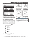
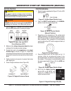
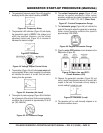
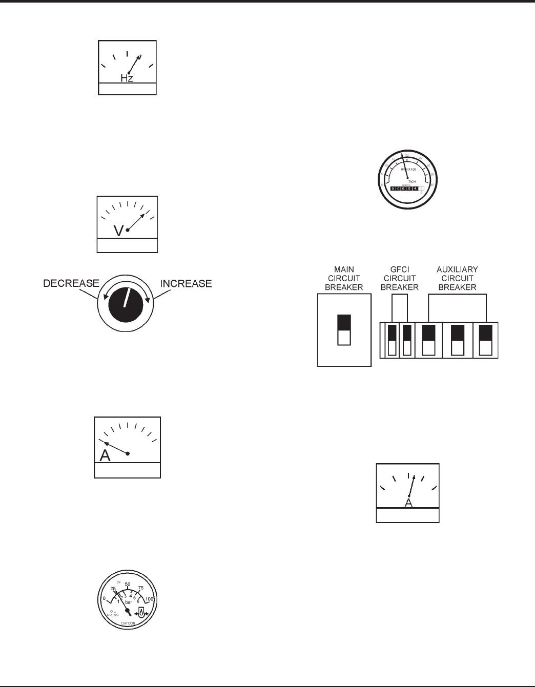
The generator’s frequency meter (Figure 42) should be 6.
displaying the 60 cycle output frequency in HERTZ.
Frequency MeterFigure 42.
The generator’s AC-voltmeter (Figure 43) will display 7.
the generator’s output in VOLTS. If the voltage is not
within the specified tolerance, use the voltage
adjustment control knob (Figure 44) to increase or
decrease the desired voltage.
VoltmeterFigure 43.
Voltage Adjust Control KnobFigure 44.
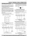
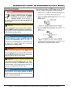
The ammeter (Figure 45) will indicate 8. zero amps with
no load applied. When a load is applied, the ammeter
will indicate the amount of current that the load is
drawing from the generator.
Ammeter (No Load)Figure 45.
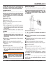
The engine oil pressure gauge (Figure 46) will indicate 9.
the oil pressure of the engine. Under normal operating
conditions the oil pressure is approximately 28 to 85
psi. (193~586 kPa).
Oil Pressure GaugeFigure 46.
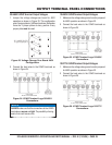
The 10. coolant temperature gauge (Figure 47) will
indicate the coolant temperature. Under normal
operating conditions the coolant temperature should
be between 167°~203°F (75°~95°C) (Green Zone).
Coolant Temperature GaugeFigure 47.
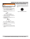
The11. tachometer gauge (Figure 48) will indicate the
speed of the engine when the generator is operating.
Under normal operating conditions this speed is
approximately 1800 RPM’s.
Engine Tachometer GaugeFigure 48.
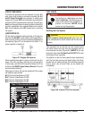
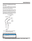
Place the 12. main, GFCI, and aux. circuit breakers in the
ON position (Figure 49).
Main, Aux. and GFCI Figure 49.
Circuit Breakers (ON)
Observe the generator’s ammeter (Figure 50) and 13.
verify it reads the anticipated amount of current with
respect to the load. The ammeter will only display a
current reading if a load is in use.
Ammeter (Load)Figure 50.
The generator will run until manually stopped or an 14.
abnormal condition occurs.