


DCA-220SSJ— OPERATION AND PARTS MANUAL — REV. #1 (03/22/07) — PAGE 53
1
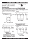
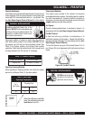
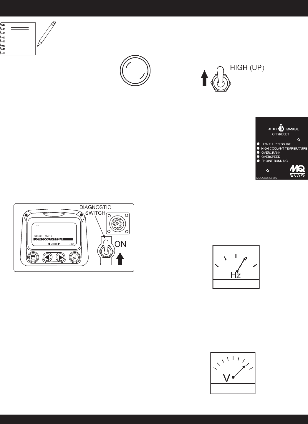
10.Verify that the Engine Running
status LED on the MPEC unit
(Figure 45) is ON (lit) after the
engine has been started.
3. If any abnormalities exists, the Warning and
Emergency Stop lamps on the Engine Operating Panel
will be lit.
4. Place the
MPEC Control Switch
(Figure 42) in the
OFF/RESET position.
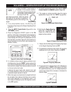
5. Place the Diagnostic ON/OFF switch in the ON
position. Verify that an Active Fault Code message is
being displayed (Diagnostic Display Panel). The fault
code message will continued to be displayed until the
fault has been corrected. Figure 43 shown below is a
typical example of an active fault code message (Low
Radiator Coolant).
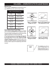
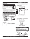
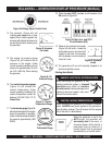
Figure 44. Engine Speed Switch (High)
When the MPEC Control switch is
placed in the manual position,
preheating of the glow plugs will begin
automatically and the preheat lamp
will stay lit until the
glow plugs are warmed. When the preheat
lamp goes off this signals the completion of
the preheating cycle and the starting of the
engine.
NOTE
Preheat Lamp
9. If the engine is running smoothly, place the engine
speed switch (Figure 44) in the “
HIGH
” (up) position.
Figure 43. Active Fault Code Message
6. In a situation where several engine problems occur
simultaneously, the word “MORE” appears above the
arrow buttons indicating that there are more fault codes
that need to be viewed. Use the arrow buttons to scroll
to the next active fault code.
If desired, the type of fault code, cause of error and
the countermeasures of the error can be referenced in
a separate engine operator’s manual.
7. Before the engine can be started, the engine fault must
be corrected. Also observe that there are no active
fault codes displayed on the diagnostic panel. If no
fault codes are displayed, place the diagnostic switch
in the OFF position.
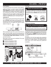
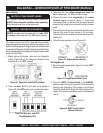
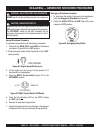
13. The generator's AC-voltmeter (Figure 47) will display the
generator’s output in VOLTS. If the voltage is not within
the specified tolerance, use the voltage adjustment
control knob (Figure 48) to increase or decrease the
desired voltage.
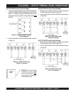
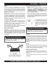
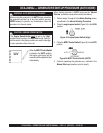
Figure 46. Frequency Meter (Hz)
12. The generator's frequency meter (Figure 46) should be
displaying the 60 cycle output frequency in HERTZ.
Figure 45. Engine Running LED (ON)
11. Observe that the Warning and Emergency Stop lamps
on the Engine Operating Panel are OFF.
8. To restart the engine due to error codes, place the
MPEC
Control Switch
in the MANUAL position (Figure 42)
Figure 47. Voltmeter
DCA-220SSJ — GENERATOR START-UP PROCEDURE (MANUAL)