


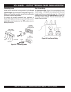
PAGE 46 — DCA-220SSJ— OPERATION AND PARTS MANUAL — REV. #1 (03/22/07)
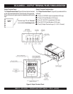
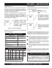
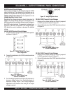
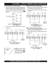
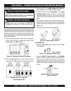
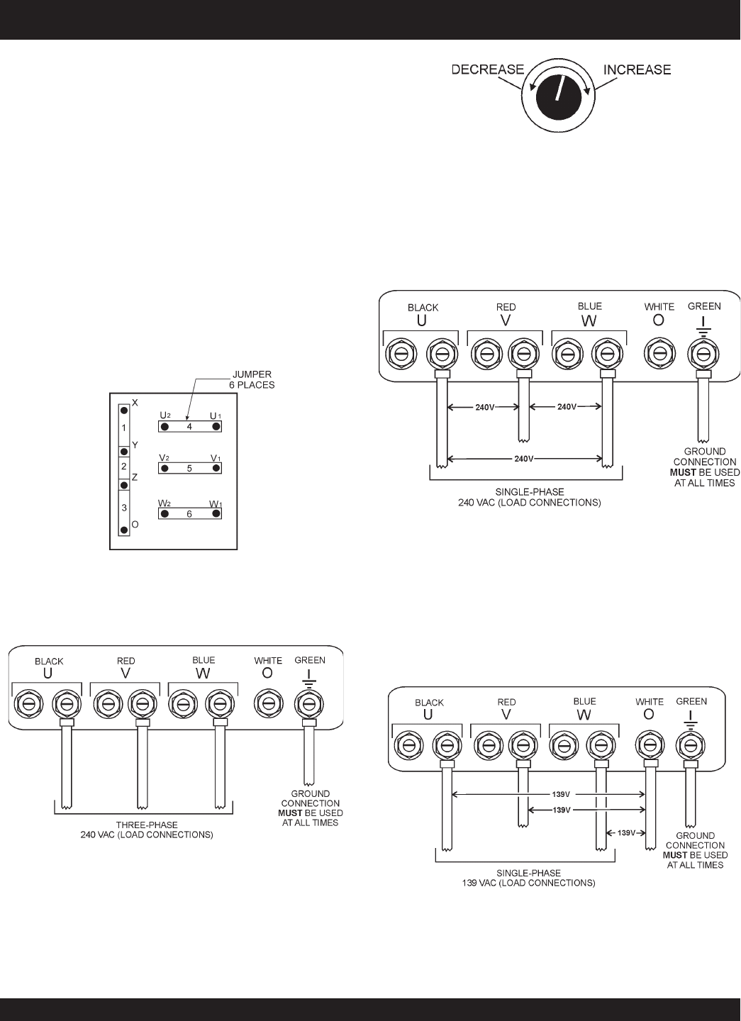
Figure 21. Voltage Change-Over Board
240V Configuration
UVWO Terminal Output Voltages
Various output voltages can be obtained using the UVWO
output terminal lugs. The voltages at the terminals are de-
pendent on the placement of the jumpers plates (6) on the
Voltage Change-Over Board
and the adjustment of the
Voltage Regulator Control Knob
.
Remember the voltage change-over board determines the
range
of the output voltage and can be configured in two
different positions that provide 6 different output voltages at
the UVWO output terminals. The generator is shipped from
the factory in the 240V configuration. The voltage regulator
(VR) allows the user to increase or decrease the selected
voltage.
3Ø-240V UVWO Terminal Output Voltages
1. Jumper the voltage change-over board for 240V operation
as shown in Figure 21.
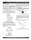
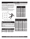
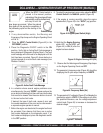
Figure 22. UVWO Terminal Lugs
3Ø-240V Connections
2. Connect the load wires to the UVWO terminals as shown
in Figure 22.
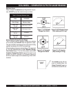
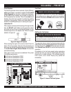
3. Turn the voltage regulator knob (Figure 23) clockwise to
increase voltage output, turn counterclockwise to
decrease voltage output. Use voltage regulator
adjustment knob whenever fine tuning of the output
voltage is required
Figure 23. Voltage Regulator Knob
1Ø-240V UVWO Terminal Output Voltages
1. Make sure the voltage change-over board is jumpered
for 240V operation as shown in Figure 21 .
2. Connect the load wires to the UVWO terminals as shown
in Figure 24.
Figure 24. UVWO Terminal Lugs
1Ø-240V Connections
Figure 25. UVWO Terminal Lugs
1Ø-139V Connections
1Ø-139V UVWO Terminal Output Voltages
1. Make sure the voltage change-over board is jumpered
for 240V operation as shown in Figure 21.
2. Connect the load wires to the UVWO terminals as shown
in Figure 25.
DCA-220SSJ — OUTPUT TERMINAL PANEL CONNECTIONS