


PAGE 26 — DCA-15SPX4— OPERATION MANUAL — REV. #0 (02/17/09)
DCA-15SPX4 — GAUGE READING/ TERMINAL PANEL CONNECTIONS
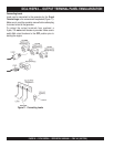
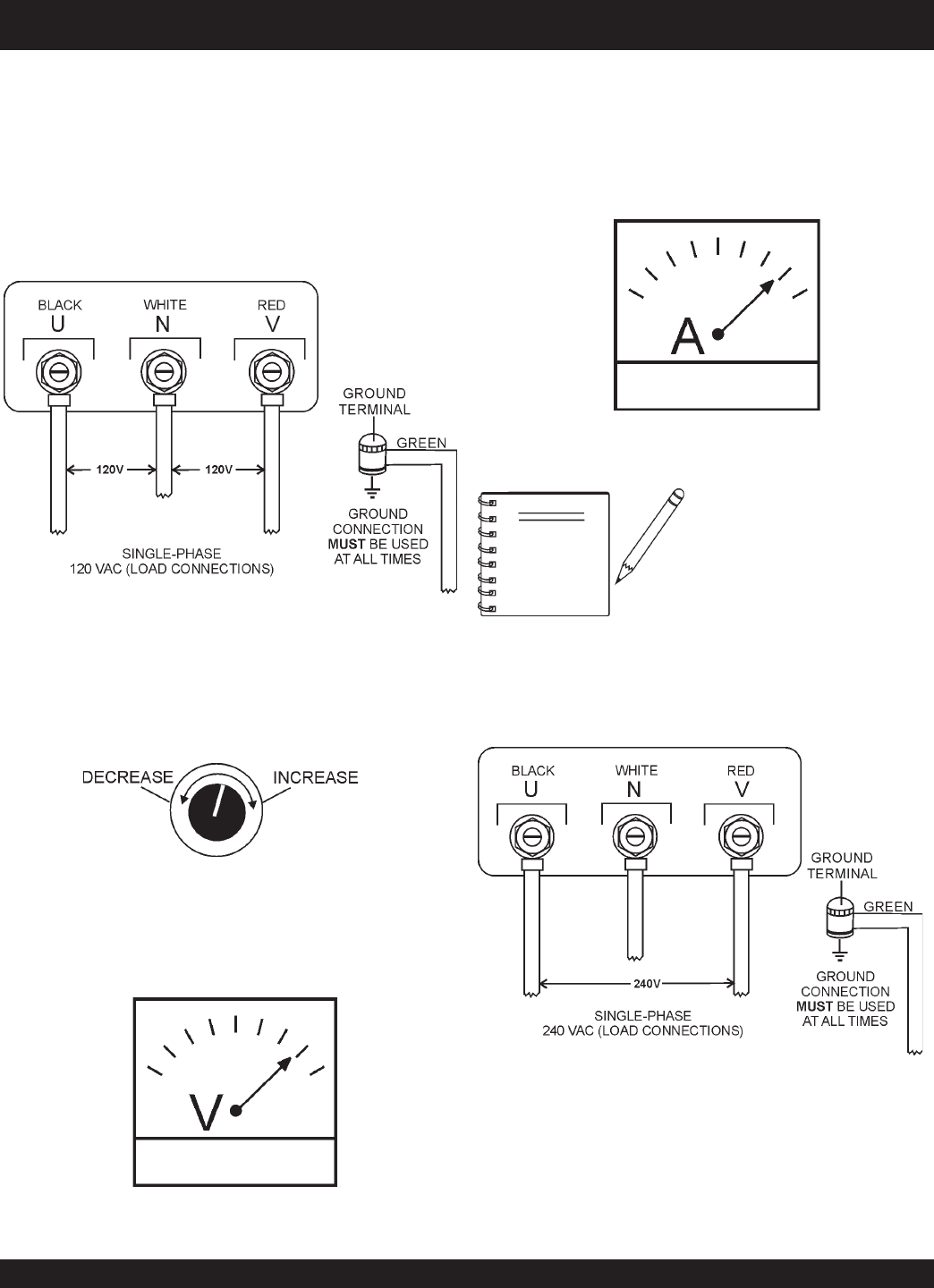
UNV Terminal Output Voltages
240/120V output voltages can be obtained using the
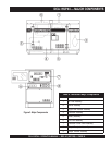
Output
Terminal Lugs
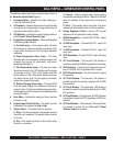
. Use the voltage regulator (VR) to either in-
crease or decrease the selected voltage.
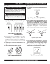
Figure 16. Output Terminal Lugs
240 VAC Single Phase Connections
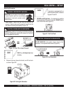
2. Turn the voltage regulator knob (Figure 13) clockwise to
increase voltage output, turn counterclockwise to
decrease voltage output.
Figure 13. Voltage Regulator Knob (139V/240V)
2. Turn the voltage regulator knob (Figure 13) clockwise to
increase voltage output, turn counterclockwise to
decrease voltage output.
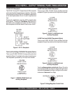
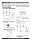
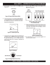
1Ø 120 Output Terminal Lug Voltages
1. Connect the load wires to the
Output Terminal Lugs
as
shown in (Figure 12)
Figure 12. Output Terminal Lugs
120 VAC Single Phase Connections
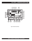
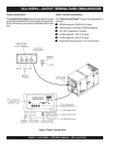
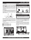
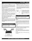
Ammeter Gauge.
The ammeter gauge (Figure 15) on the generator control panel
has been provided to help observe how much current (amps)
is being supplied to the load from the
output terminal lugs
,
GFCI receptacle or any auxulliary receptacles if installed.
Figure 15. AC Ammeter
The
ammeter
gauge will only
show a reading when the
Output
Terminal Lugs
or auxillary
receptacles are connected to a
load.
NOTE
1Ø 240 Output Terminal Lug Voltages
1. Connect the load wires to the
Output Terminal Lugs
as
shown in (Figure 16)
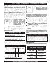
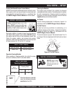
3. Observe that the output voltage either increases or
decreases by monitoring the voltmeter (Figure 14)
reading.
Figure 14. AC Voltmeter