


DCA-15SPX4— OPERATION MANUAL — REV. #0 (02/17/09) — PAGE 21
1
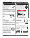
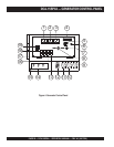
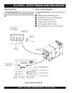
The definitions below describe the controls and functions of
the
Generator Control Panel
(Figure 4).
1. Frequency Meter – Indicates the output frequency in
hertz (Hz). Normally 60 Hz.
2. AC Ammeter – Indicates the amount of current the load
is drawing from the generator per leg selected by the
ammeter phase-selector switch.
3. AC Voltmeter – Indicates the output voltage present at
the
U,O, and V Output Terminal Lugs
.
4. Engine Warning Lamp Module – This module displays
the following engine failures:
A. Pre-Heat Lamp – As the engine cranks, this lamp
will illuminate to indicate automatic preheating of the
engine. When the lamp turns off, the engine has been
preheated.
B. Water Temperature Alarm Lamp – This lamp
indicates when the emergency shutdown system has
stopped the engine for abnormally high water
temperature(234 deg. F).
C. Oil Pressure Alarm Lamp – This lamp is on when
the starter switch is in the “ON” position and the engine
oil pressure is low(7.1 PSI). It will indicate when the
starter switch is in the “ON” position, before the engine
has been started, and if the emergency shutdown
system has stopped the engine.
D. Battery Charging Alarm Lamp – This lamp is ON
when the output voltage of the alternator drops tob an
unusual value. If this lamp indicates during operation,
the emergency shutdown system immediately operates
to stop the engine.
5. Hour Meter – Indicates the number of hours machine
has been in use.
6. Engine Speed Control Switch – This switch controls
the speed of the engine from
idle
to high.
7. Starter Switch – This switch has four positions.
A. Stop – The switch should be in this position anytime
the unit is not in operation. This position allows removal
of the key.
B. Run – The switch should be in this position when
the unit is in operation.
DCA-15SPX4 — GENERATOR CONTROL PANEL
C. Preheat – Use this position before starting during
cold weather operating conditions. Observe the Preheat
Lamp for indication of the proper time for starting the
engine.
D. Start – This position starts the engine, and when
released will automatically return to the run position.
8. Voltage Regulator Control – Allows ±15% manual
adjustment of the generator’s output voltage.
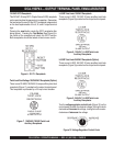
9. CS6369 Receptacle – Provides 240/120 VAC output
(50 amps max).
10. L6-30R Receptacle – Provides 240 VAC output (30
amps max).
11. L5-30R Receptacle – Provides 120 VAC output (30
amps max).
12. GFCI Receptacle – Provides 120 VAC output (20 amps
max).
13. AC Circuit Breaker - This two-pole, 50A breaker is
provided to protect the CS6369 receptacle from overload.
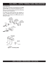
14. UNV Terminals - Connect load to these terminals AC
load for 120/240 VAC single phase 60 Hz. output.
15. GFCI Ground Terminal - Use this terminal to ground
the generator
16. AC Circuit Breaker - This two-pole, 30A breaker is
provided to protect the auxillary receptacle (for L6-30R)
from overload.
17. AC Circuit Breaker - This single-pole, 30A breaker is
provided to protect the auxillary receptacle (for L5-30R)
from overload.
18. AC Circuit Breaker - This single-pole, 20A GFCI breaker
is provided to protect the GFCI receptacle (5-20R) from
overload.
19. AC Circuit Breaker – This three-pole, 70A main breaker
is provided to protect the the
U,N, and V Output
Terminal Lugs
from overload.