


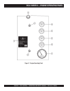
PAGE 30 — DCA-100SSVU— OPERATION AND PARTS MANUAL — REV. #0 (11/05/07)
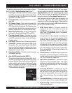
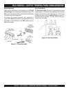
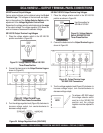
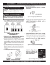
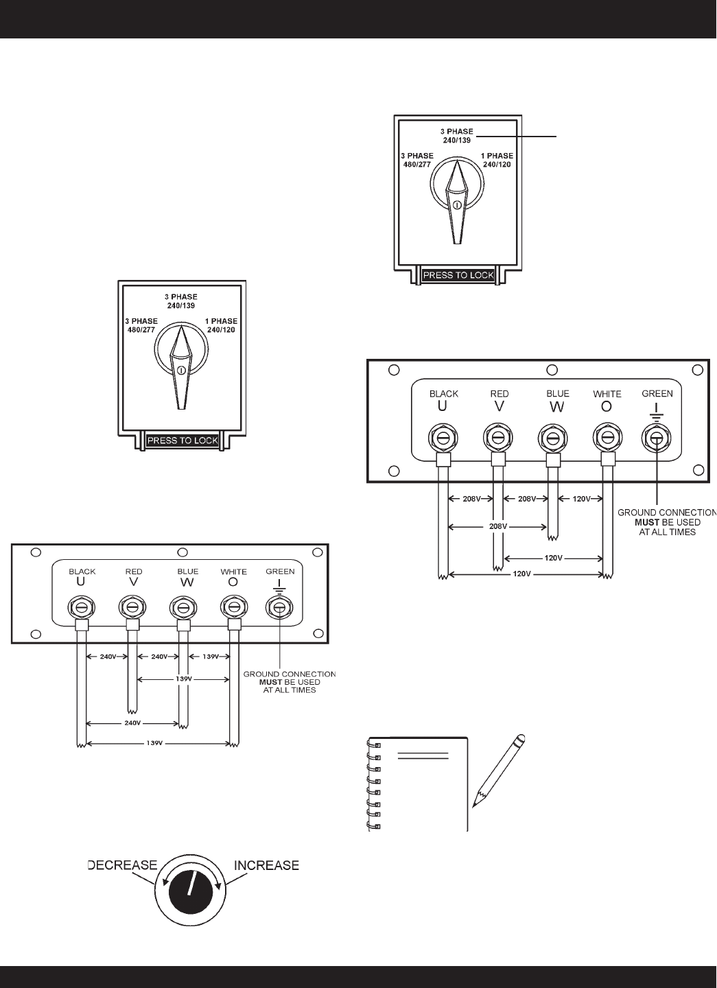
Figure 22. Voltage Selector Switch 240/139V
Three-Phase Position
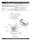
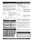
DCA-100SSVU — OUTPUT TERMINAL PANEL CONNECTIONS
UVWO Terminal Output Voltages
Various output voltages can be obtained using the
Output
Terminal Lugs
.. The voltages at the terminals are depen-
dent on the position of the
Voltage Selector Switch
and the
adjustment of the
Voltage Regulator Control Knob
.
Remember the voltage selector switch determines the
range
of the output voltage. The voltage regulator (VR) allows the
user to increase or decrease the selected voltage.
3Ø 240/139 Output Terminal Lug Voltages
1. Place the voltage selector switch in the 3Ø 240/139
position as shown in (Figure 22).
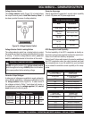
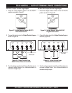
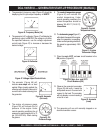
Figure 23. Output Terminal Lugs
240/139V Three Phase Connections
2. Connect the load wires to the
Output Terminal Lugs
as
shown in (Figure 23).
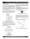
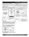
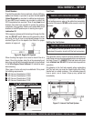
3. Turn the voltage regulator knob (Figure 24) clockwise to
increase voltage output, turn counterclockwise to
decrease voltage output.
3Ø 208V/1Ø120V Output Terminal Lug Voltages
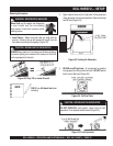
1. Place the voltage selector switch in the 3Ø 240/139
position as shown in Figure 25.
Figure 24. Voltage Regulator Knob (139V/240V)
Use this position for
3Ø-208 or 1Ø120V.
2. Connect the load wires to the
Output Terminal Lugs
as
shown in Figure 26.
NOTE
To achieve a 3Ø 208V output
the voltage selector switch
must be in the 3Ø-240/139
position and the voltage
regulator must be adjusted to
208V.
Figure 26. Output Terminal Lugs
3Ø-208V/120V Connections
Figure 25. Voltage Selector
Switch 3Ø-208V/1Ø-120V
Three-Phase Position
3. Turn the voltage regulator knob (Figure 25) clockwise to
increase voltage output, turn counterclockwise to
decrease voltage output.