


DCA-100SSVU— OPERATION AND PARTS MANUAL — REV. #0 (11/05/07) — PAGE 23
1
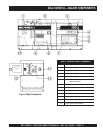
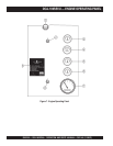
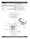
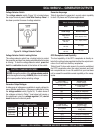
DCA-100SSVU — ENGINE OPERATING PANEL
The definitions below describe the controls and functions of
the DCA-100SSVU
Engine Operating Panel
(Figure 7).
1. Panel Light – Normally used in dark areas or at night
time. When activated, panel lights will illuminate. When
the generator is not in use be sure to turn the panel
light switch to the OFF position.
2. Panel Light Switch – When activated will turn on control
panel light.
3. Oil Pressure Gauge – During normal operation this
gauge be should read between 44 to 73 psi. (303~503
kPa). When starting the generator the oil pressure may
read a little higher, but after the engine warms up the oil
pressure should return to the correct pressure range.
4. Water Temperature Gauge – During normal operation
this gauge be should read between 165° and 203°F.
5. Charging Ammeter Gauge – Indicates the current
being supplied by the engine’s alternator which provides
current for generator’s control circuits and battery
charging system.
6. Fuel Gauge - Indicates amount of diesel fuel available.
7. Tachometer – Indicates engine speed in RPM’s for 60
Hz operation. This meter should indicate 1800 RPM’s
when the rated load is applied. In addition a built in hour
meter will record the number of operational hours that
the generator has been in use.
8. Engine Speed Switch – This switch controls the speed
of the engine (low/high).
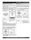
A. MPEC Control Switch – This switch controls the
running of the unit. If this switch is set to the
OFF/RESET position, the unit will not run. When this
switch is set to the MANUAL position, the generator
will start immediately.
If the generator is to be connected to a building’s AC
power source via an automatic transfer switch
(isolation), place the switch in the AUTO position. In
this position, should an outage occur, the automatic
transfer switch (ATS) will start the generator
automatically via the generator’s auto-start contacts
connected to the ATS’s start contacts. Please refer to
your ATS installation manual for further instructions for
the correct installation of the auto-start contacts of the
generator to the ATS.
B. Low Oil Pressure – Indicates the engine pressure has
fallen below 15 psi. The oil pressure is detected using
variable resistive values from the oil pressure sending
unit. This is considered a
major
fault.
C. High Coolant Temperature – Indicates the engine
temperature has exceeded 239
°
F. The engine
temperature is detected using variable resistive values
from the temperature sending unit. This is considered
a
major
fault.
D. Overcrank Shutdown – Indicates the unit has
attempted to start a pre- programmed number of times,
and has failed to start. The number of cycles and
duration are programmable. It is pre-set at 3 cycles
with a 10 second duration. This is considered a
major
fault.
E. Overspeed Shutdown – Indicates the engine is running
at an unsafe speed. This is considered a
major
fault.
F. Engine Running – Indicates that engine is running at
a safe operating speed.
If the engine does not engage (start) by the third attempt,
the engine will be shutdown by the engine controller’s
Over
Crank Protection
mode. If the engine engages at a speed
(RPM's) that is not safe, the controller will shutdown the
engine by initializing the
Over Speed Protection
mode.
Also the engine controller will shut down the engine in the
event of low oil pressure, high coolant temperature, low
coolant level, and loss of magnetic pickup. These conditions
can be observed by monitoring the LED status indicators on
the front of the controller module.
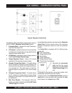
9. Auto On/Off Engine Controller (MPEC) –
This controller has a vertical row of status LED's (inset),
that when lit, indicate that an engine malfunction (fault)
has been detected. When a fault has been detected the
engine controller will evaluate the fault and all major
faults will shutdown the generator. During
cranking
cycle
, The MPEC will attempt to crank the engine for
10 seconds before disengaging.