


GB113BC GLOBUG LIGHTING SYSTEM — OPERATION AND PARTS MANUAL — REV. #5 (01/16/12) — PAGE 17
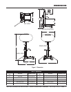
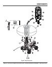
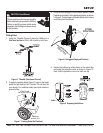
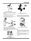
Figure 5 shows the location of the controls and components
for the GloBug Lighting System. The functions of each control
is described below:
1. Steering Handle – The GloBug can be moved in either
a forward or reverse direction by pulling back or pushing
forward on the T-handle. In addition the front wheels are
designed to turn in the opposite direction of the T-handle
placement thus allowing the GloBug to turn either left or
right.
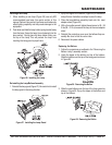
2. Mast Winch – Use this mechanical winch to raise and
lower the mast. Always be on the lookout for overhead
obstructions. Keep immediate area free of bystanders
and debris when raising the mast.
3. Lamp Power Cable (Generator) – Connect this quick-
disconnect cable plug (generator-side) to the lamp power
cable plug.
4. Mast – This mast is comprised of three separate stages.
The mast can be raised in excess of 14.58 ft. (4.44
meters). Again when raising the mast, always be on the
lookout for overhead obstructions.
5. Lift Hanger – When lifting of the GloBug is required
always use a suitable lifting device of adequate lifting
capability. NEVER stand underneath the GloBug while it
is being lifted.
6. Generator – MQ GA-Series type generator. This genera-
tor will supply the necessary power to run the GloBug. For
operation of generator read generator Operation Manual
supplied with GloBug.
7. Tires – The GloBug uses 4 pneumatic type tires. Replace
with only recommended type tire . NEVER allow the rear
tires to go flat. This could adversely affect the braking
system. Inflate tires to 35.5 psi (245kPa).
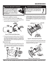
8. Locking Clamps – To secure the generator to the
GloBug cart platform, place clamps (4) around the pipe
frame of the generator. Tighten securely to prevent
movement.
9. Brake Pad – When the brake pedal is pressed, this pad
will strike and hold the rear tires in place. Make sure rear
tires are inflated to the correct air pressure.
10. Outriggers – ALWAYS deploy the outriggers when
raising the mast.
11. Brake Pedal – Step on this pedal to apply the brakes. To
release the brakes, press down on brake pedal again.
12. ON/OFF Switch – Place this switch in the ON position
to turn on the lamp. To turn off the lamp place in the down
position (OFF). Please wait for approximately 10 minutes
before attempting to turn the lamp back on.
13. Power Cable – Connect this cable to a 120 VAC, 60 Hz
power source.
14. Balloon Storage Bag – Store the balloon in this storage
bag when the GloBug is not in use. Allow a sufficient
amount of time for the lamp to cool down before placing
balloon inside storage bag. Possibility exists of balloon
getting burned.
15. Balloon – This balloon is made of heat resistant nylon,
with a diameter of 3.9 ft. (1,150 mm). The balloon shall be
inflated to a pressure of 31.26 psi (215.6 kPA).
16. Lamp Power Cable (Balloon) – Connect this quick-
disconnect cable plug (balloon-side) to the generator
power cable plug.
17. Fan Motor (Blower) – This electric motor is responsible
for inflating the balloon. It will supply a pressure of 31.26
psi (215.6 kPA). Please note that the balloon will begin to
inflate as soon as power is applied to the GloBug. The
OFF/ON switch
does not
control the electric fan motor.
18. Lamp Guard – This guard (cage) protects the lamp from
being hit by objects.
19. Lamp – 1000 watt metal-halide type lamp. Replace with
only MQ recommended type lamp. Always allow a
sufficient amount of time for the lamp to
cool down
before changing.
20. Lamp Holder – Screw lamp into this holder. If lamp
becomes difficult to screw into holder or holder is
damaged, replace holder.
21. Balloon Alarm Buzzer – Will sound during normal
operation if the balloon attempts to make contact with the
lamp's
hot!
surface. If this condition occurs, immediately
place the GloBug's ON/OFF switch in the OFF position.
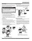
22. Adjust Lever – This lever allows the lamp to be posi-
tioned up or down. Turn counterclockwise to release lamp
and position. Turn clockwise to tighten.
23. Ballast Compartment – Provides the necessary elec-
tronics to light the lamp. To gain access to the ballast
compartment the generator must be removed from the
cart platform.
COMPONENTS