


English Operating Manual for Wood Splitter
3
• Tighten the castellated nut until it
is tight, then slacken it by approx.
1
/
3
revolution and until one of the
slots in the nut is facing the hole
in the axle.
• On both wheels insert a cotter pin
through the slot in the nut and
through the hole in the axle and
secure by bending out the ends.
Note: The wheels should rotate
freely and there should be no
lateral play.
Place the caps on the hubs and tap
into place with a rubber mallet.
Attention!
The maximum tyre pressure is
2 bar. The tyre pressure should always
be the same for both tyres.
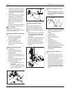
Attaching the mudguards (optional)
Fig. 1
• Remove nuts, lock washers,
washers and hexagon bolts
from the mudguards.
• Attach mudguards to the
hydraulic tank with bolts,
washers, lock washers and nuts
from step 1.
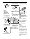
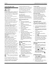
Attaching the connecting rod
Figs. 2a and 2b
• Remove the bolts (2) and
nuts (4) from the front of the
hydraulic tank.
• Position the connecting rod (3)
and attach with the bolts and nuts
from step 1.
• Lower the hydraulic tank (1) and
place on the attached wheels.
• Fold out the support:
– Remove the spring cotter (7)
and pin (8).
– Fold out the support (5) and
fix to the connecting rod with
the pin and spring cotter.
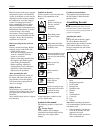
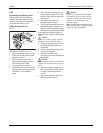
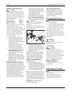
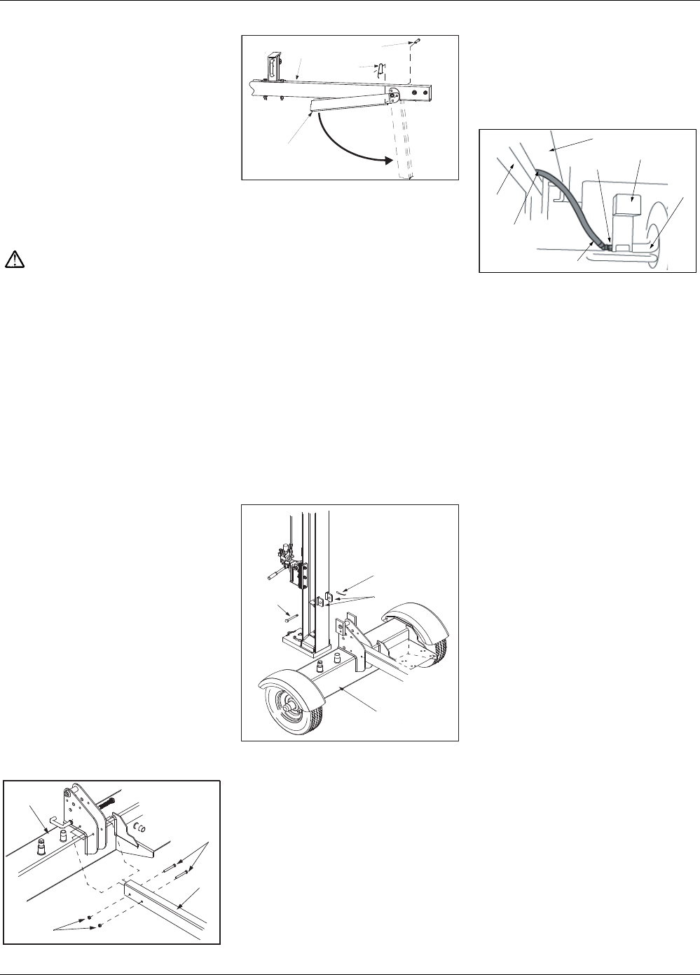
Attaching the splitting column
Fig. 3
Place the unit consisting of the
splitting wedge, splitting column
and cylinder in an upright position.
Note: Two persons may be required
for this.
• Remove the pin (1) and cotter pin
(2) from the holders and position
the hydraulic tank (4) relative to
the column.
• Insert the pin, which has just been
removed, through the holders on
the splitting column and the
holder on the hydraulic tank unit.
Secure with cotter pin (bend out
the ends).
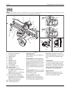
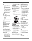
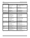
Attaching the high-pressure hoses
Fig. 4
• Remove the protective cap from
the connecting piece on the side of
the pump (a little oil may flow out
of the pump).
1 Position of the high-pressure hose
between connecting rod and
column
2 Connecting rod
3 Splitting column
4 Hose connecting piece
5 Pump
6 Intake hose
7 High-pressure hose
• The high-pressure hose is
connected to the control valve.
Feed the hose between the column
and the connecting rod and
connect to the connecting piece
on the pump.
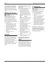
Attaching the return-flow hose
Fig. 5
• Loosen the hose clip (2) on the
free end of the return-flow hose
and remove the protective insert
from the end of the hose.
• Remove the protective cap from
the connecting piece at the top of
the filter head. Attach the end of
the hose to the connecting piece
(at the top of the filter head) and
secure with the hose clip (tighten
well).
Fig.3
1
4
3
2
Fig.4
1
6
5
3
2
7
4
1
4
3
2
Fig. 2a
Fig. 2b
5
8
7
6