


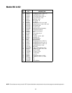
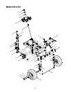
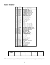
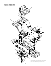
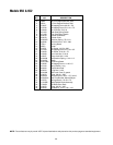
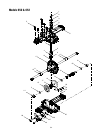
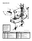
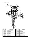
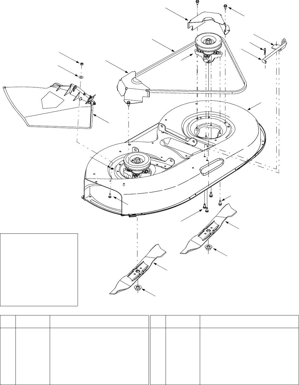
36
Model
s 650 & 652
†
Refer to
E
†
on Page 30
14
13
17
16
11
11
10
E
†
1
2
9
7
12
15
8
8
6
6
4
5
3
REF.
NO.
PART
NO. DESCRIPTION
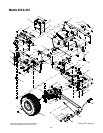
1 618-0138A Spindle Assembly
2 683-04003A Deck Shell
3 710-0726 Self-tapping Screw, 5/16-12 x .75
4 710-1260A Screw, 5/16-18 x .75
5 710-1611B Self-tapping Screw, 5/16-18 x .75
6 712-0417A Hex Flange Nut, 5/8-18
7 714-04023 Internal Cotter Pin, .080 x 1.56
8 742-0610A Blade, 21.23”
9 747-04018A Deck Hanger Link/Anti-sway Rod
10 754-0329A Deck Belt
11 783-04148A Belt Cover
12 783-04211 Anti-sway Stabilizer Bracket
13 736-0270 Bell Washer, .265 x .75 x .062
14 712-3006 Hex Nut, 1/4-20
15 726-0233 Push Nut, 1/4
16 731-1032B Discharge Chute Assembly
17 710-0751 Hex Cap Screw:1/4-20 x .620
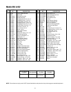
REF.
NO.
PART
NO. DESCRIPTION
IMPORTANT:
For a proper
working machine, use
Factory Approved Parts.
V-belts are designed to
engage and disengage
safely. A substitute (non
OEM) V-belt can be
dangerous by not
disengaging completely.