


15
The cutting deck engagement may be adjusted to make
certain the deck is disengaged when deck
engagement/lift lever is in the BLADES STOP position.
Correct adjustment as follows.
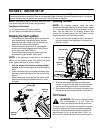
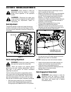
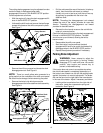
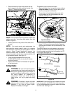
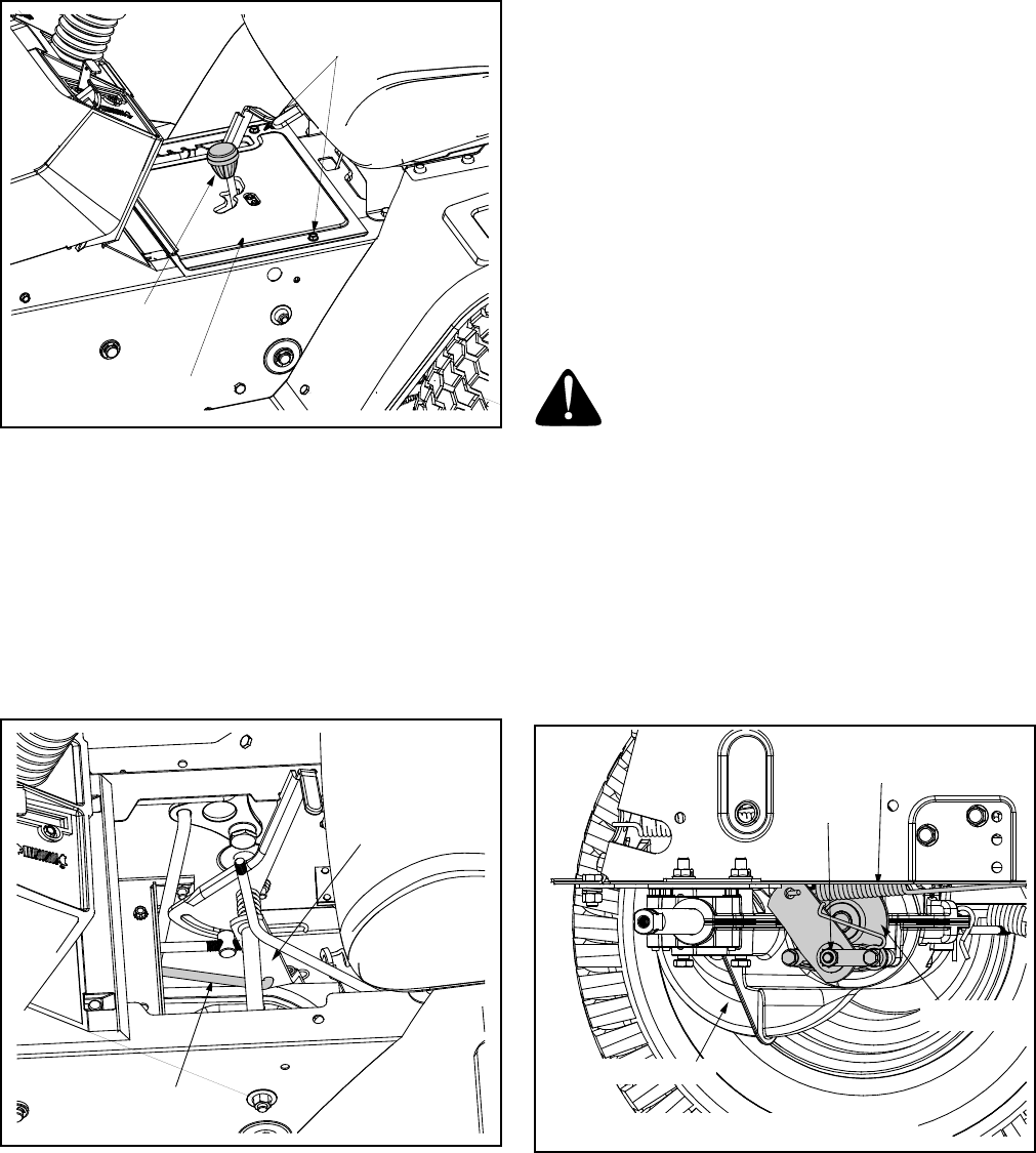
• With the engine off, place the deck engagement/lift
lever in the BLADES OFF position.
• Unthread the shift knob and remove the two flange
screws which secure the shift cover panel in place.
See Figure 7.
Figure 7
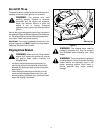
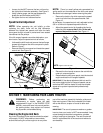
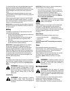
• Remove the shift cover panel and locate the deck
disengagement rod. See Figure 8.
NOTE: There is a small yellow wire connected to a
spring switch on the underside of the shift cover panel.
Be careful not to damage it when removing the panel.
• Remove the hairpin clip which secures the
disengagement rod to the stabilizer shaft assembly.
See Figure 8.
Figure 8
• Pull the rod toward the rear of the tractor (to take up
slack), then thread the rod inward or outward
(usually only one or two turns) until the rod lines up
as precisely as possible with the hole in the
stabilizer shaft.
NOTE: Threading the disengagement rod outward
(toward the rear of the tractor) provides for more belt
tension. Threading the disengagement rod inward
provides for less belt tension.
• Reinsert the ferrule and re-secure the rod with the
cotter pin removed earlier.
Check the adjustment by placing the deck engagement/
lift lever in the BLADES STOP position. The deck
should move up and forward, allowing the belt to
become loose.
• Reassemble the shift cover panel.
• Start the tractor’s engine and test the deck
engagement/lift lever to be certain the blades fully
disengage when in the BLADES STOP position.
• Repeat the adjustment procedure if necessary.
Parking Brake Adjustment
WARNING: Never attempt to adjust the
brakes while the engine is running. Always
disengage PTO, move shift lever into neutral
position, stop engine and remove key to
prevent unintended starting.
If the tractor does not come to a complete stop when
the clutch-brake pedal is completely depressed, or if
the tractor’s rear wheels can roll with the parking brake
applied, the brake is in need of adjustment. The brake
disc can be found on the right side of the transmission
in the rear of the tractor. Adjust if necessary as follows:
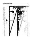
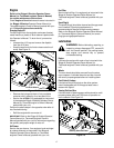
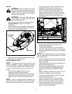
• Looking at the transmission from the right side of
the tractor, locate the compression spring and
brake disc. See Figure 9.
Figure 9
Shift Knob
Flange Screws
Shift Cover Panel
Disengagement Rod
Stabilizer Shaft
Assembly
Hex Nut
Compression
Spring
NOTE: Rear, right wheel not shown for clarity
Transmission
Brake Disc