


21
Deck Belt
WARNING: Shut the engine off, remove
ignition key, set the parking brake, disconnect
the spark plug wire(s) and ground against the
engine to prevent unintended starting before
removing the cutting deck.
WARNING: Always wear safety glasses or
safety goggles to protect your eyes while
removing the cutting deck.
• Remove the cutting deck from the tractor (Refer to
Cutting Deck Removal on page 18, for detailed
instructions).
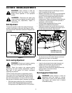
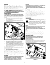
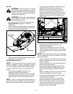
• Remove the belt guards (located over each spindle
pulley) by removing the self-tapping screws which
secure them in place. See Figure 20.
Figure 20
• Remove and replace the belt, reassemble following
the instructions in reverse order.
Drive Belts (Upper and Lower)
NOTE: The engine pulley must be removed from the
engine’s crankshaft in order to change the tractor’s
drive belts. Doing so requires an air/impact wrench.
It is recommended that both belts be changed at the
same.
• Place the deck engagement/lift lever in the
engaged (all the way forward) position.
• Unthread the shift knob and remove the two flange
screws which secure the shift cover panel in place.
Refer to Figure 7. Remove the shift cover panel.
NOTE: There is a small yellow wire connected to a
spring switch on the underside of the shift cover panel.
Be careful not to damage it when removing the panel.
• Using a spring puller (Part No. 732-0571)or other
suitable tool, disconnect the spring which is
attached to a small hook found on the left, rear
portion of the transmission. Refer to Figure 14.
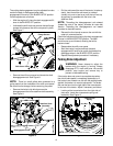
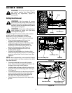
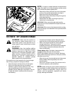
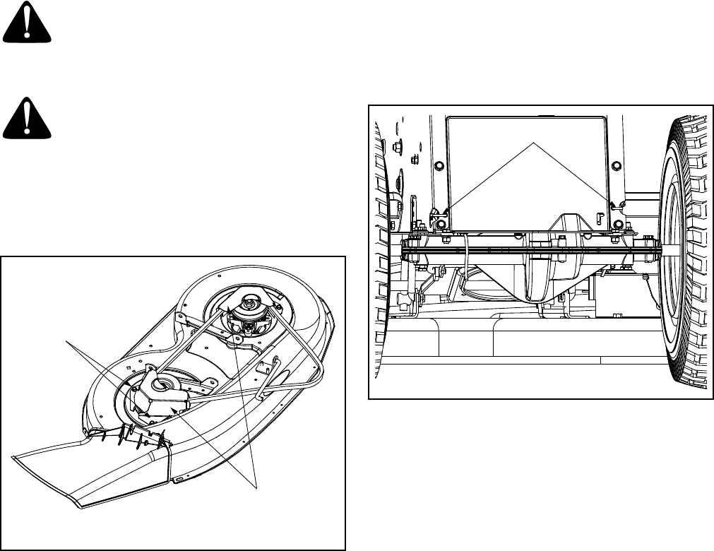
• Using a spring puller (Part No. 732-0571)or other
suitable tool, disconnect the two springs which are
attached to the rear portion of the tractor frame.
See Figure 21.
Figure 21
• Place the deck engagement/lift lever in the
BLADES STOP position.
• Locate the two belt keeper pins, found on either
side of the engine pulley, and use a 1/4-inch socket
wrench to remove them from the lower frame. Refer
to Figure 15.
NOTE: When reassembling, make certain belt keeper
pins are assembled in the same locations from which
they were removed.
• Using an impact gun with a 5/8-inch socket, remove
the hex screw with secures the engine pulley to the
engine crankshaft.
• Carefully lower the pulley off of the crankshaft and
remove the belt from around it.
• Disconnect the battery cables from the terminals
(disconnect the NEGATIVE (Black) wire from it’s
terminal first, followed by the POSITIVE (Red)
wire).
• Detach the battery hold-down rod and remove both
the battery and battery tray from the tractor.
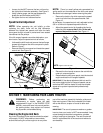
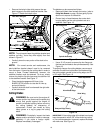
• Locate the transmission pulley though the battery
tray opening. See Figure 22.
• Using an impact gun with a 13/16-inch socket,
remove the pulley from the transmission’s input
shaft by removing the flange nut which secures it
• Carefully lift the pulley off of the transmission’s
input shaft and remove the upper drive belt from
around it and the variable speed.
Self-Tapping
Screws
Belt Guards
Springs