


19
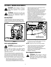
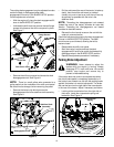
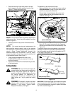
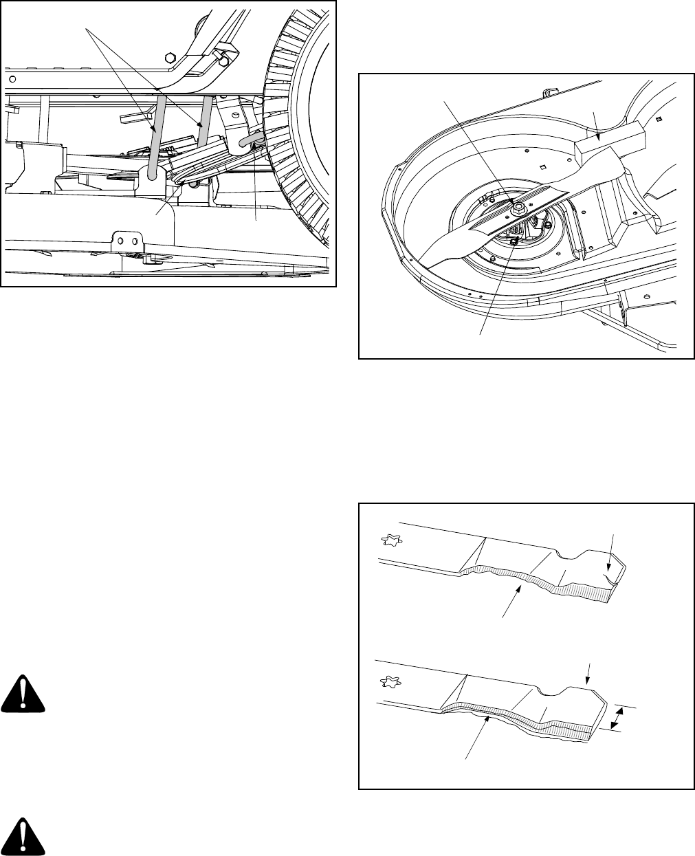
• Remove the hairpin clips which secure the rear
deck hangers to the deck stabilizer bracket. See
Figure 17. Retain the hairpin clips.
Figure 17
NOTE: The style and shape the stablizer bracket and
stablizer rod vary. Yours may differ slightly from that
shown in Figure 17.
• Carefully lower the rear portion of the deck to the
ground.
NOTE: For normal service and maintenance, the
deck stabilizer bracket doesn’t need to be removed
from the tractor. If removing the cutting deck in order to
mount a Snow Thrower attachment, however, the
stabilizer bracket must be removed. To do so, simply
remove the hairpin clip which secures the stabilizer rod
to the stabilizer bracket. See Figure 17.
• Place the deck engagement/lift lever in the
BLADES STOP position to raise the lift links up,
and out of the way.
• Carefully slide the deck from beneath the right side
of the lawn tractor.
Cutting Blades
WARNING: Be sure to shut the engine off,
remove ignition key, disconnect the spark plug
wire(s) and ground against the engine to
prevent unintended starting before removing
the cutting blade(s) for sharpening or
replacement. Protect your hands by using
heavy gloves or a rag to grasp the cutting
blade.
WARNING: Periodically inspect the blade
adapter and/or spindle for cracks or damage,
especially if you strike a foreign object.
Replace immediately if damaged
.
The blades may be removed as follows.
• Remove the deck from beneath the tractor, (refer to
Cutting Deck Removal on page 18) then gently flip the
deck over to expose its underside.
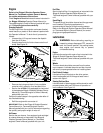
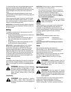
• Place a block of wood between the center deck
housing baffle and the cutting blade to act as a
stabilizer. See Figure 18.
Figure 18
• Use a 15/16" wrench to remove the hex flange nut
that secures the blade to the spindle assembly. See
Figure 18.
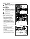
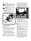
To properly sharpen the cutting blades, remove equal
amounts of metal from both ends of the blades along
the cutting edges, parallel to the trailing edge, at a 25°
to 30° angle. See Figure 19.
Figure 19
IMPORTANT:
If the cutting edge of the blade has already
been sharpened to within 5/8" of the wind wing radius,
or if any metal separation is present, replace the blades
with new ones. See Figure 19.
Rear Deck Hangers
Stabilizer Rod
Stabilizer Bracket
Spindle Assembly
Hex Flange Nut
Wood Block
Blade Separation
Worn Blade Edge
Wind Wing
Sharpen Edge Evenly
5
/
8
"
m
i
n
i
m
u
m