


Self-propelled Chipper Shredder Vacuum
5
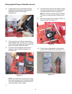
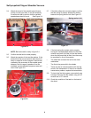
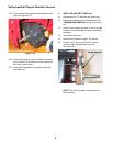
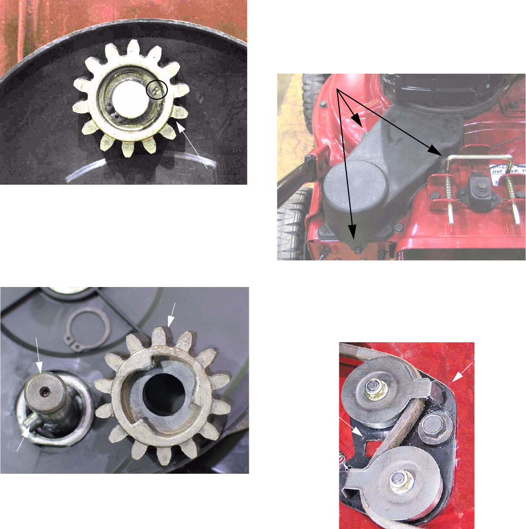
2.11. Confirm that the drive gears are installed on the
correct side. See Figure 2.11.
NOTE: There is an “R” on the right side gear and
an “L” on the left side gear.
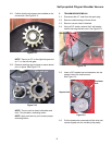
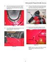
2.12. Remove retaining ring and gear to assure dowel
pin is in place. See Figure 2.12.
NOTE: The pin must be free to slide back and
forth. This provides a ratcheting action.
NOTE: Apply anti-sieze to pin to ensure proper
ratcheting action.
Figure 2.11
Right hand drive gear
Figure 2.12
Right side gear
Drive axle
Pin
3. TRANSMISSION REMOVAL
3.1. Disconnect the H.T. lead from the spark plug.
3.2. Remove collection bag or blower chute.
3.3. Remove vacuum hose if attached.
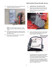
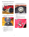
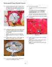
3.4. Using a 3/8” socket, remove the 3 self tapping
screws securing the belt cover. See Figure 3.4.
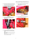
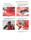
3.5. Insert a 3/8” breaker bar and extension into the
square hole of the tensioner arm.
See Figure 3.5.
3.6. Pull the breaker bar rearward until the drive belt
can be slipped over the variable pulley easily
Figure 3.4
Self tapping screws
Figure 3.5
Square hole
Tensioner
Arm