


9
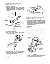
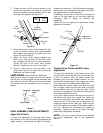
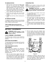
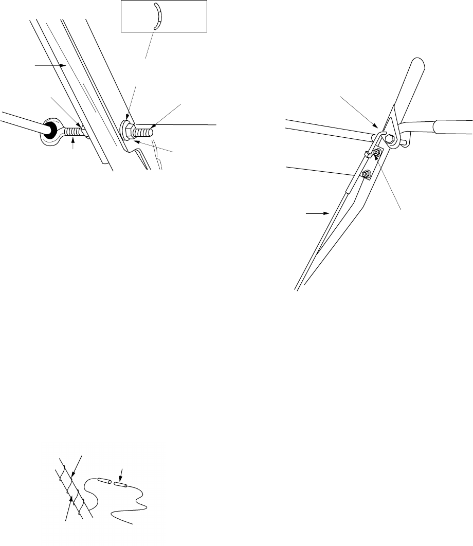
3. Thread one hex nut (D) onto the eyebolt on the
chute crank assembly until there is at least two
inches of threads showing between the nut and
the head of the eyebolt. See Figure 10.
Figure 10
4. Place the eyebolt into the hole located half way
up the left handle. Secure with cupped washer
(N) (cupped side against the handle, see inset,
Figure 10) and hex nut (D).
5. Adjust the chute crank support bracket (see
Figure 9) so that the spiral on the chute crank
fully engages the teeth on the chute assembly.
Tighten the nuts on the chute crank bracket
securely. Tighten the hex nuts on the eyebolt.
6. Check to make sure all nuts and bolts on the
control panel and all four bolts which secure the
handles to the frame are tight.
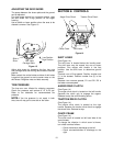
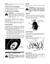
LAMP WIRING
(Models E645 and E665 only)
Wrap the wire from the lamp down the right handle
until the wire can be plugged into the alternator lead
wire under the fuel tank. Be sure the lamp wire does
not interfere with the movement of any controls or
cables.
Figure 11
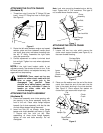
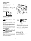
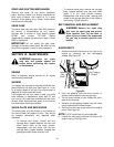
FINAL ASSEMBLY AND ADJUSTMENTS
Auger Drive Clutch
To check the adjustment of the auger drive clutch,
push forward on the left hand clutch grip (depress the
rubber bumper). There should be slack in the cable.
Release the clutch grip. The cable should be straight.
Make certain you can depress the auger drive clutch
grip against the left handle completely.
If necessary, loosen the hex lock nut and thread the
cable in (for less slack) or out (for more slack) as
necessary. Refer to Figure 12. Recheck the
adjustment.
Tighten the lock nut against the cable when correct
adjustment is reached.
Figure 12
Traction Drive Clutch and Shift Lever
Adjustment
To check the adjustment of the traction drive clutch
and shift lever, move the shift lever all the way over
to fifth (5) position. With the traction drive lever
released, push the snow thrower forward. The unit
should move forward freely. Then engage the traction
drive clutch grip. The wheels should stop turning.
Now release the traction drive clutch grip, and push
the unit again. Move the shift lever back to the fast
reverse position, then all the way over again. There
should be no resistance in the shift lever, and the and
the wheels should keep turning
If you have resistance when moving the shift lever or
the wheels stop when they should not, loosen the
jam nut on the traction drive cable and unthread the
cable one turn. If the wheels do not stop when you
engage the traction drive clutch grip, loosen the jam
nut on the traction drive cable and thread the cable in
one turn. Recheck the adjustment and repeat as
necessary. Tighten the jam nut to secure the cable
when correct adjustment is reached.
NOTE:
If you are uncertain that you have reached
the correct adjustment, refer to the Adjustment
section.
Cup
Side
Crown
Side
Left
Handle
Hex Nut
(D)
2” of
Threads
Cupped
Washer (N)
Eyebolt
Hex Nut
(D)
Lamp Wire
Alternator
Lead
Right Handle
“Z” Fitting
Hex Bolt
Cable