


10
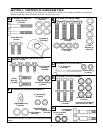
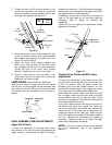
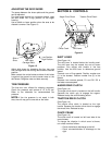
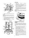
ADJUSTING THE SKID SHOES
The space between the shave plate and the ground
can be adjusted.
For close snow removal on a smooth surface, raise
the skid shoes into a high position on the auger
housing.
Use a middle or lower position when the area to be
cleared is uneven. See Figure 13.
Figure 13
Adjust skid shoes by loosening the four hex nuts
and carriage bolts and moving skid shoes to desired
position.
Make certain the entire bottom surface of skid shoe
is against the ground to avoid uneven wear on the
skid shoes. Retighten nuts and bolts securely.
TIRE PRESSURE
The tires are over inflated for shipping purposes.
Check tire pressure and reduce to 15 to 20 psi.
Refer to tire sidewalls for recommended tire
pressure.
NOTE:
If the tire pressure is not equal in both
tires, the unit may pull to one side or the other.
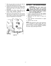
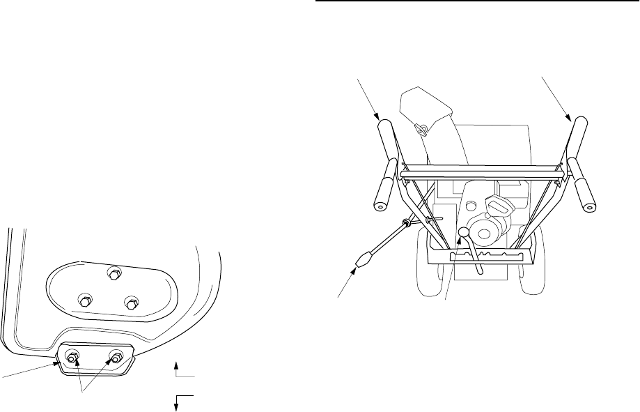
SECTION 6: CONTROLS
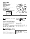
Figure 14
SHIFT LEVER
(See Figure 14)
The shift lever is located below the handle panel.
The shift lever may be moved into one of seven
positions. Run engine with throttle in the fast
position. Use the shift lever to determine ground
speed.
Forward—one of five speeds. Position number one
(1) is the slowest. Position number five (5) is the
fastest.
Reverse—two reverse speeds; R1 and R2. R2 is
the faster reverse speed.
AUGER DRIVE CLUTCH
(See Figure 14)
The auger drive clutch is located on the left handle.
Squeeze the clutch grip to engage the augers.
Release to stop the snow throwing action.
TRACTION DRIVE CLUTCH
(See Figure 14)
The traction drive clutch is located on the right
handle. Squeeze the traction drive clutch to engage
the wheel drive. Release to stop.
CHUTE CRANK
(See Figure 14)
The chute crank is located on left hand side of the
snow thrower.
To change the direction in which snow is thrown,
turn chute crank as follows:
• Crank clockwise to discharge to the left.
• Crank counterclockwise to discharge to the
right.
Hex
Nuts
Carriage
Bolts
Skid
Shoe
Low Position
High Position
Auger Drive Clutch Traction Drive Clutch
Chute Crank
Shift Lever