


13
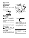
TO ENGAGE DRIVE
1. With the engine running near top speed, move
shift lever into one of the five FORWARD
positions or two REVERSE positions. Select a
speed appropriate for the snow conditions that
exist. Use the slower speeds until you are
familiar with the operation of the snow thrower.
2. Squeeze the auger clutch grip and the augers
will turn. Release it and the augers will stop.
3. Squeeze the drive clutch grip and the snow
thrower will move. Release it and drive motion
will stop.
4. NEVER move shift lever without releasing drive
clutch.
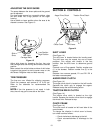
TO ENGAGE AUGERS
To engage the augers and start the snow throwing
action, squeeze the auger clutch grip against the left
handle. Release to stop the augers.
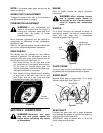
TIRE CHAINS (Optional Equipment)
Tire chains should be used whenever extra traction
is needed.
OPERATING TIPS
NOTE: Allow the engine to warm up for a few
minutes as the engine will not develop full power
until it reaches operating temperature.
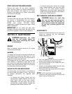
WARNING: Temperature of muffler
and surrounding areas may exceed 150
degrees Fahrenheit. Avoid these areas.
1. For most efficient snow removal, remove snow
immediately after it falls.
2. Discharge snow downwind whenever possible.
Slightly overlap each previous swath.
3. Set the skid shoes 1/4" below the scraper bar
for normal usage. The skid shoes may be
adjusted upward for hard-packed snow. Adjust
downward when using on gravel or crushed
rock.
4. Be certain to follow the precautions listed under
‘‘To Stop Engine’’ to prevent possible freeze-up.
5. Clean the snow thrower thoroughly after each
use.
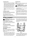
SECTION 8: ADJUSTMENTS
WARNING: NEVER attempt to clean
chute or make any adjustments while
engine is running.
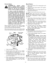
CHUTE ASSEMBLY ADJUSTMENT
The distance snow is thrown can be controlled by
adjusting the angle of the top section of the chute
assembly.
SKID SHOE ADJUSTMENT
The space between the shave plate and the ground
can be adjusted. Refer to the Final Assembly and
Adjustments section.
TRACTION DRIVE CLUTCH
ADJUSTMENT
Refer to the Final Assembly and Adjustments
section to adjust the traction drive clutch. If you are
uncertain that you have reached the correct
adjustment, the adjustment can be physically
checked as follows.
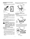
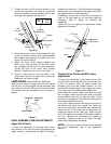
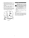
1. With the snow thrower tipped forward (be
certain to drain the oil and gasoline or drain the
oil and place plastic film under the gas cap if the
snow thrower has already been operated),
remove the frame cover underneath the snow
thrower by removing six self-tapping screws.
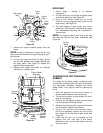
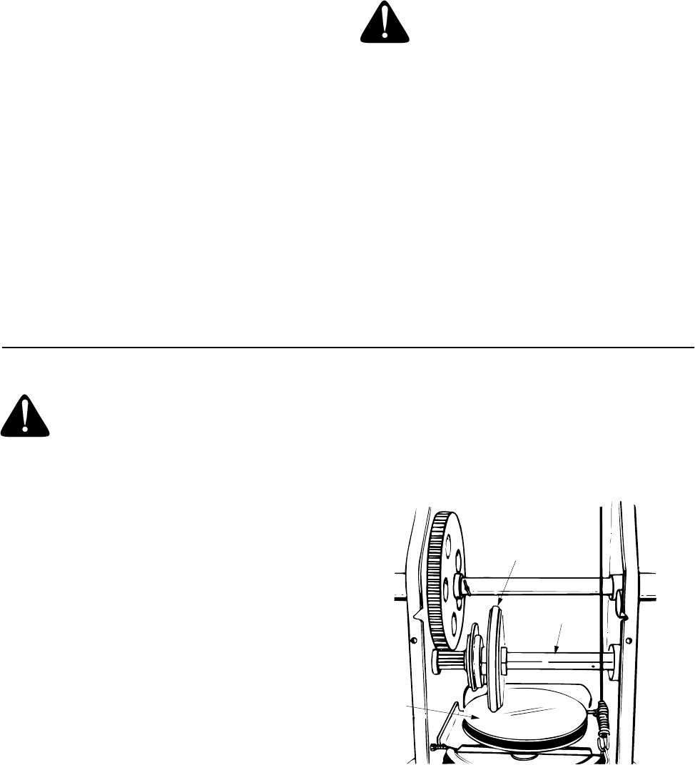
2. With the traction drive clutch released, there
must be clearance between the friction wheel
and the drive plate in all positions of the shift
lever. With the traction drive clutched engaged,
the friction wheel must contact the drive plate.
See Figure 18.
Figure 18
3. If adjustment is necessary, loosen the lock nut
on the traction drive cable and thread the cable
in or out as necessary. Tighten the lock nut to
secure the cable when correct adjustment is
reached. Reassemble the frame cover.
Friction
Wheel
Gear Shaft
Drive
Plate