


15
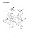
DRIVE AND SHIFTING MECHANISM
Remove rear cover. Oil any chains, sprockets,
gears, bearings, shafts, and shifting mechanism at
least once a season. Use engine oil or a spray
lubricant. Avoid getting oil on rubber friction wheel
and aluminum drive plate.
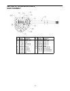
GEAR CASE
The worm gear case has been filled with grease at
the factory. If disassembled for any reason,
lubricate with 2 ounces of Shell Alvania grease
EPR00, part number 737-0168. Before
reassembling, remove old sealant and apply “Loctite
5699” or equivalent.
IMPORTANT: Do not overfill the gear case.
Damage to the seals could result. Be sure the vent
plug is free of grease in order to relieve pressure.
SECTION 10: MAINTENANCE
WARNING: Disconnect the spark
plug wire and ground against the
engine before performing any repairs
or maintenance.
ENGINE
Refer to separate engine manual for all engine
maintenance procedures.
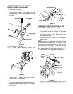
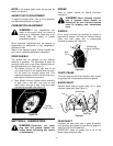
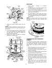
AUGERS
The augers are secured to the spiral shaft with two
shear bolts and hex lock nuts. See Figure 21. If you
hit a foreign object or ice jam, the snow thrower is
designed so that the bolts will shear.
If the augers will not turn, check to see if the bolts
have sheared. A replacement shear bolt (P) and
hex lock nut (Q) have been provided with the snow
thrower. When replacing bolts, spray an oil lubricant
into shaft before inserting new bolts.
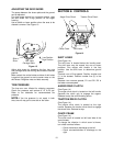
SHAVE PLATE AND SKID SHOES
The shave plate and skid shoes on the bottom of
the snow thrower are subject to wear. They should
be checked periodically and replaced when
necessary.
• To remove skid shoes, remove the four
carriage bolts, cupped washers and hex nuts
which attach them to the snow thrower.
Reassemble new skid shoes with the four
carriage bolts, cupped washers (cupped side
goes against skid shoes) and hex nuts.
• To remove shave plate, remove the carriage
bolts, cupped washers and hex nuts which
attach it to the snow thrower housing.
Reassemble new shave plate, making sure
heads of the carriage bolts are to the inside of
the housing. Tighten securely.
BELT REMOVAL AND REPLACEMENT
WARNING: Remove the spark plug
wire from the spark plug and ground.
Drain gasoline from the fuel tank, or
place a piece of plastic film underneath
the gas cap to prevent gasoline from
leaking.
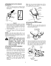
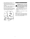
AUGER BELTS
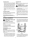
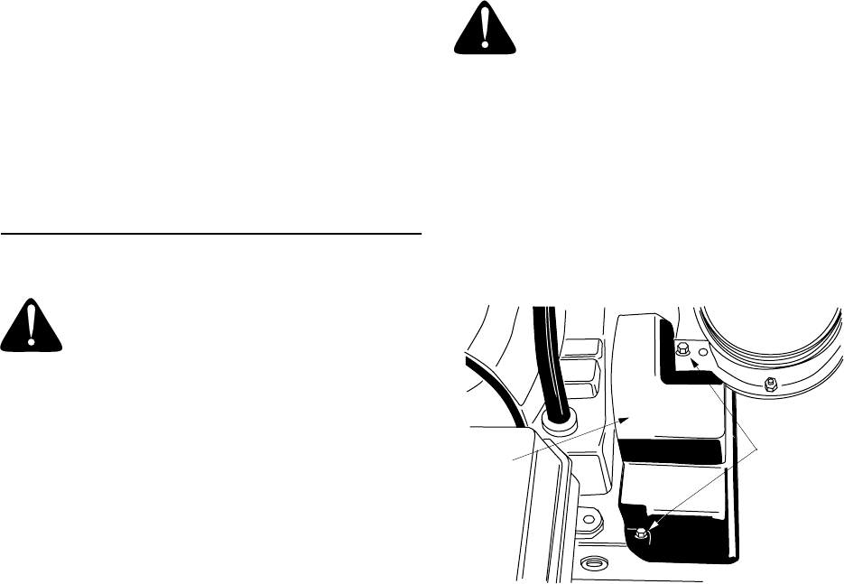
1. Remove the plastic belt cover on the front of the
engine by removing the two self-tapping
screws. See Figure 22.
Figure 22
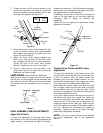
2. Drain the gasoline from the snow thrower, or
place a piece of plastic under the gas cap.
3. Tip the snow thrower up and forward so that it
rests on the housing.
4. Remove six self-tapping screws from the frame
cover underneath the snow thrower.
5. Roll the front and rear auger belts off the engine
pulley. See Figure 23.
NOTE: 5.0 HP model has only one auger belt.
6. Unhook the idler spring from the hex bolt on the
auger housing. See Figure 24.
Self-Tapping
Screws
Cover
Belt