


9
7
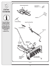
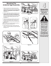
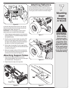
Mounting
Auger
Housing
All Models
Before installing
attachment, place
tractor on a firm and
level surface. Place
the PTO in the disen-
gaged (OFF) position,
set the parking brake,
shut engine off and
remove key to prevent
unintended starting.
WARNING
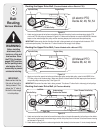
Figure 6–9
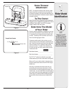
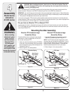
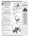
Attaching Reflectors
Peel off the backing from each of the reflectors to
expose the adhesive surface. Adhere the reflectors to
the rear of the tractor’s fender (one on the left and one
on the right) so that the reflectors simulate taillights.
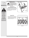
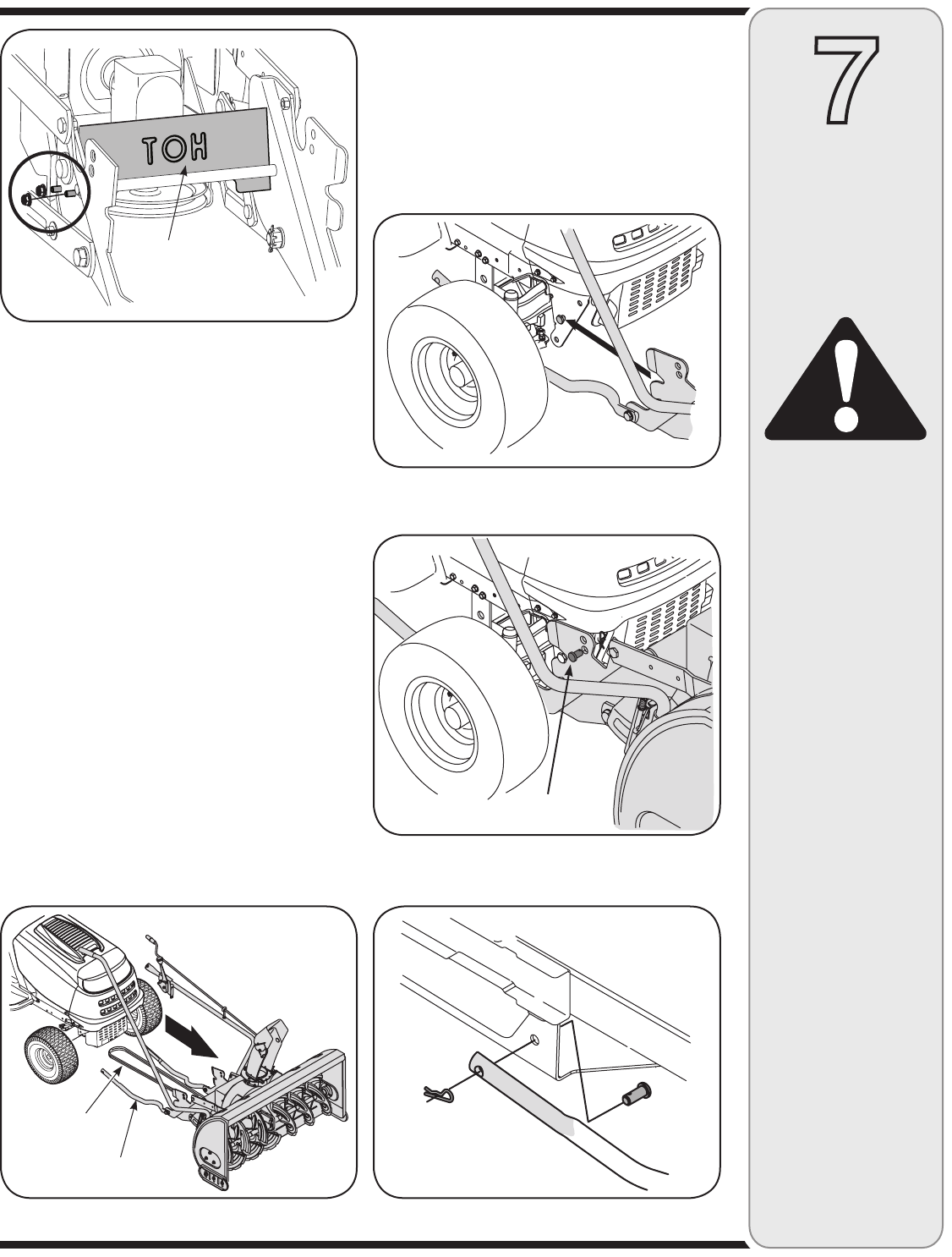
remove the heat shield remove the four lock nuts and
bolts (two on either side of the unit) securing the heat
shield to the lift linkage. See figure 6–5.
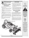
IMPORTANT: It will be necessary to have a second
person assist you to complete the following steps.
1. Position the auger housing assembly in front of the tractor
as seen in Figure 6–6. Lay the belt and support tubes on
the installation surface.
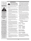
2. Carefully move the tractor forward (by pushing, NOT
driving it) so that support tubes found on the rear of
the auger housing assembly are positioned between
the tractor’s front tires. Set the parking brake.
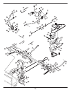
3. With the help of an assistant, lift up the auger housing
and move it so that it rests over the shoulder bolts found
on tractor See Figure 6–7.
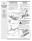
4. Maneuver the auger housing until the mounting holes
line up. Insert the clevis pins from your hardware pack
and secure with a click pins. See Figure 6–8.
Attaching Support Tubes
1. Secure the left support tube to the front of the
undercarriage assembly with the clevis pin and hairpin
clip removed earlier. See Figure 6–9.
2. Repeat the previous step on the right side.
Figure 6–6
Figure 6–7
Heat Shield
Figure 6–5
Figure 6–8
Support Tube
Belt
Clevis Pin