


6
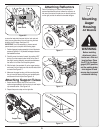
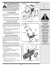
Before installing
attachment, place
tractor on a firm
and level surface.
Place the PTO in
the disengaged
(OFF) position, set
the parking brake,
shut engine off and
remove key to prevent
unintended starting.
4
Assembly
Model Series
600-649 &
All 800 series.
WARNING
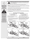
WARNING: Before installing attachment, place tractor on a firm and level surface. Place the
PTO in the disengaged (OFF) position, set the parking brake, shut engine off and remove key
to prevent unintended starting.
NOTE: References to LEFT and RIGHT indicate the left and right sides of the tractor when facing forward in the
operator’s position. Reference to the FRONT indicates the grille end; to the REAR the drawbar end.
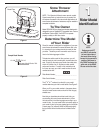
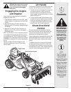
IMPORTANT: You must first figure out which model of rider you are attaching this snow thrower to. Refer to Determine
Your Model of Rider on page 3 of this manual to determine what model rider you are attempting to install this attachment
to. Then proceed to the applicable instructions for your model of rider.
Your tractor’s cutting deck, PTO belt and front deck stabilizer bracket must be removed prior to mounting the snow
thrower attachment. Refer to your tractor’s Operator’s Manual for detailed instructions. If your tractor is equipped with
any front-end accessory (i.e. front bumper kit), it must also be removed.
Do you have an Electric PTO or Manual PTO?
If you engage your tractor’s cutting deck by using your left hand to pivot a lever forward, your tractor has a Manual
PTO. If you engage your tractor’s cutting deck by pulling outward on a small knob located on the tractor’s dash, your
tractor has an Electric PTO.
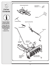
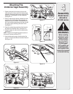
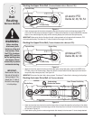
Electric PTO Undercarriage
Assembly Setup
Proceed as follows when mounting this snow thrower
attachment to a tractor equipped with a 42, 46, 50 or
54-inch deck with electric PTO:
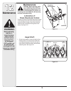
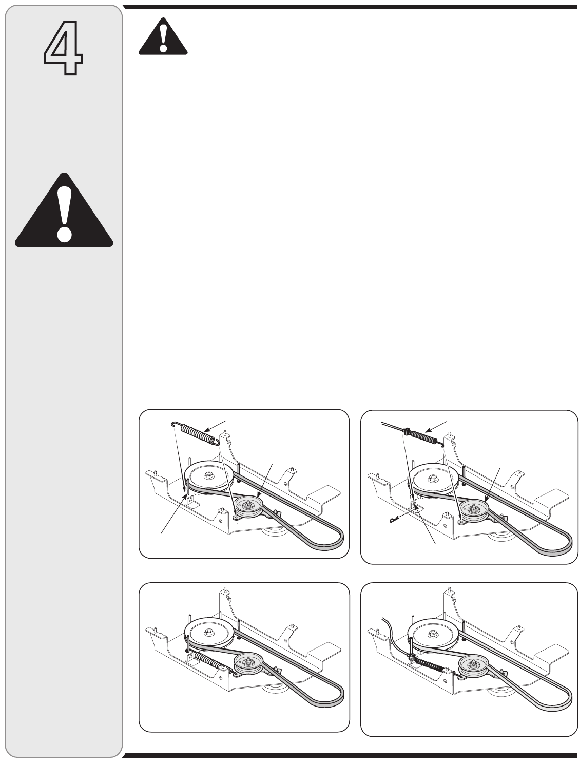
1. Attach one end of the extension spring (732-0594A)
to the hole in the idler assembly. Mount the opposite
end of the extension spring to the belt keeper pin as
illustrated in Figure 4–1.
2. Refer to Figure 4–2 for correct position.
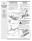
Manual PTO Undercarriage
Assembly Setup
1. Attach the PTO cable to the idler bracket, then fit the
cable into the slotted fitting as seen in Figure 4–3.
NOTE: The PTO cable should be hanging down under
you tractor after you removed the mowing deck. You will
need to slide the undercarriage unit under your tractor in
position for which it will be mounted. The slanted side
should be pointed towards the front of your tractor.
2. Refer to Figure 4–4 for correct position.
Mounting the Idler Assembly
Figure 4–1
Idler Pulley &
Idler Bracket
PTO Cable
Belt Keeper Pin
Slotted Fitting
Figure 4–2
Figure 4–3
Figure 4–4
Extension Spring
Idler Pulley &
Idler Bracket