


8
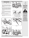
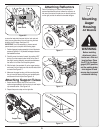
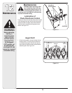
Mounting Auger Assembly
WARNING: Before installing
attachment, place tractor on a firm
and level surface. Place PTO in the
disengaged (OFF) position, set the
parking brake, shut engine off and remove key to
prevent unintended starting.
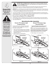
IMPORTANT: If you are installing this snow thrower
attachment on any tractor model with a side discharge
muffler, See Figure 6–4, then the heat shield on the
auger housing must be removed. See figure 6–5. To
6
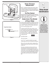
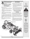
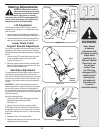
Assembling
Controls
NOTE:
All references to left
or right side of the
snow thrower is
from the operating
position only.
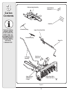
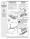
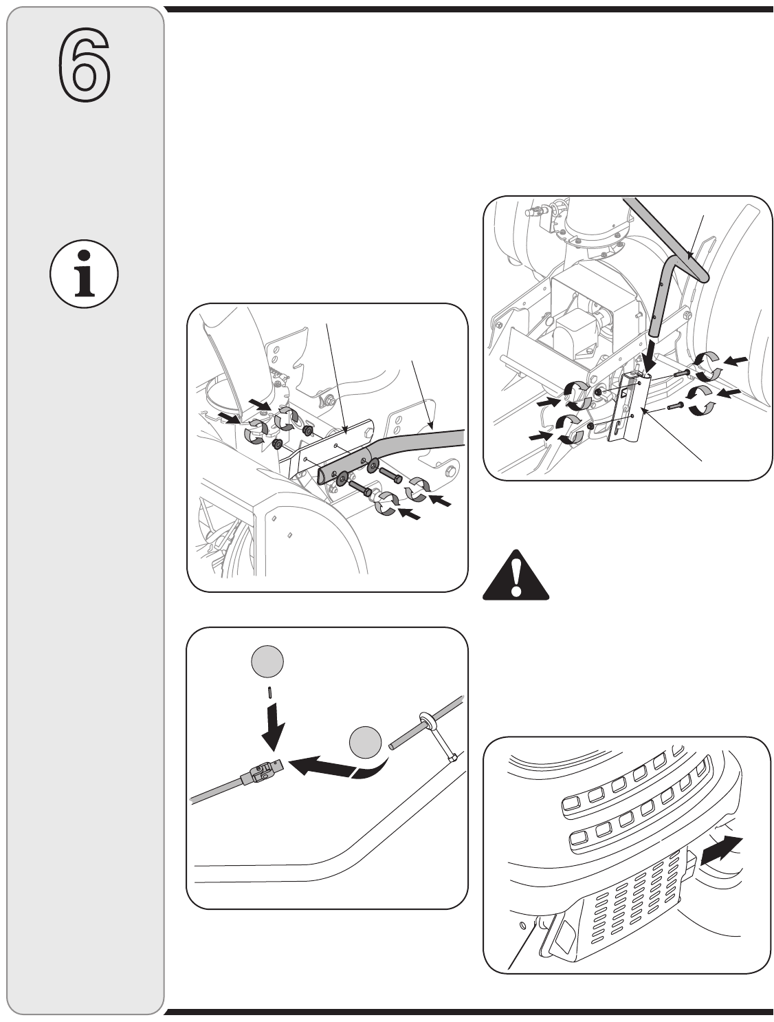
Figure 6–1
Figure 6–3
Chute Directional
Control Assembly
Upper Lift Link
Lift Handle
Auger Housing Assembly
Attaching
Lift Handle
1. Attach lift handle to lift bracket on the right side of
auger housing assembly with two hex screws and two
flange nuts provided. See Figure 6–3.
2. Fasten the lift cable to the lift handle with two of the
cable ties provided. Pull the cable ties until snug and
trim excess.
Attaching Chute
Directional Control
1. Attach the chute directional control assembly to the
upper lift link on the left side of the auger housing.
Assemble with two hex screws and washers as
illustrated in Figure 6–1. Secure with two flange nuts.
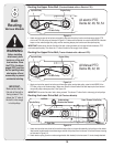
1. Secure the upper chute crank rod to the joint block
(A) on the lower chute crank rod with the cotter pin
(B) provided. See Figure 6–2.
3. Fasten chute tilt cables to chute directional control
with two of the cable ties provided. Pull cable ties
until snug and trim excess.
A
B
Figure 6–2
Figure 6–4