


7
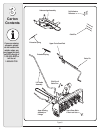
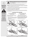
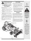
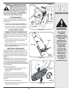
Before installing
attachment, place
tractor on a firm
and level surface.
Place the PTO in
the disengaged
(OFF) position, set
the parking brake,
shut engine off and
remove key to prevent
unintended starting.
4
Assembly
Model Series
600-649 &
All 800 series.
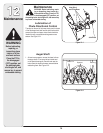
WARNING
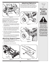
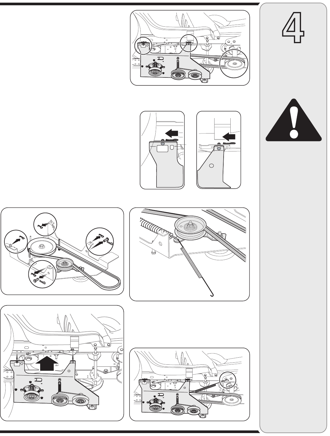
Mounting The
Undercarriage Assembly
1. Remove and retain the four hairpin clips from the
weld pins found on the top side of the undercarriage
assembly. Remove and retain the two clevis pins with
hairpin clips. This hardware is for later installation.
See Figure 4–5.
2. With the undercarriage assembly beneath the tractor,
see figure 4–6, lift the undercarriage assembly up
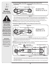
against the frame of the tractor. The weldpins on the
top of the undercarriage assembly should go through
the aligning holes found along the tractor’s frame.
See Figure 4–7.
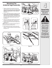
3. Fasten the undercarriage assembly to the frame with
the hairpin clips removed in step 1. See figure 4–8
4. Route the upper drive belt around the engine pulley.
See Figure 4–7.
NOTE: Proceed to the Assembling Controls section of
this manual if you have an Electric PTO.
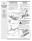
5. Attach the extension spring to the idler pulley. See
figure 4–9. Connect the other end to tractor’s frame rail.
See Figure 4–10.
Figure 4–5
Figure 4–6
Figure 4–7
Figure 4–8
Figure 4–9
Figure 4–10