


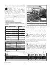

ADJUSTMENTS
WARNING: DISCONNECT PTO DRIVE SHAFT AND HYDRAULIC HOSES (RELIEVE HYDRAULIC
PRESSURE) BEFORE CLEANING, ADJUSTING, LUBRICATING OR SERVICING THIS SPREADER. FAILURE
TO HEED MAY RESULT IN SERIOUS PERSONAL INJURY OR DEATH.
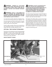
FRONT DRIVE ROLLER CHAINS
There are six roller chain drives located at the front of the spreader. Regularly check that all tensioning springs are in
serviceable condition for automatic roller chain tightening. Manually adjust spring tensioners (as needed) by turning
double locknuts on all tensioning bolt/idler assemblies. Proper roller chain tension is when 1/4" to ½" deflection
occurs on the slack side of the chain. Regularly re-check all roller chain tensions. Keep all roller chains tight at all
times! For clarity purposes, the following illustrations detail each roller chain reduction separately.
NOTE: The side bars of the roller chains will wear into the idler nylon rollers up to the rollers of the roller chain forming
grooves. These grooves will serve as a guide when the roller chain loosens due to normal use. From this point on,
after tightening, the idler nylon rollers should run for hundreds of hours without any noticeable wear.
Model 8720/8865 -17-
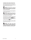
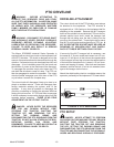
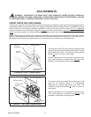
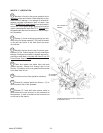
FIGURE 7. SECOND CHAIN DRIVE
IDLER NYLON
ROLLER
ROLLER CHAIN
LH TOP SPROCKET
SPRING LOADED
ADJUSTER
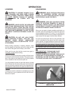
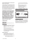
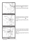
The first chain drive (PTO input shaft to the large RH top
sprocket, figure 8) is automatically tensioned by a spring
loaded idler nylon roller. The extension spring should
extend 2”
from its neutral 5” total length.
Manual adjustment for the automatic tensioning idler,
nylon roller assembly is located at the left rear
of the
spreader’s front bearing mounting plate.
The second chain drive (large RH top sprocket to the
large LH top sprocket, figure 7) is automatically
tensioned by a spring loaded idler nylon roller. The
extension spring should extend 2
“ from its neutral 5"
total length.
Manual adjustment for the automatic tensioning idler,
nylon roller assembly is located at the left rear
of the
spreader’s front bearing mounting plate.
FIGURE 8. FIRST CHAIN DRIVE
RH TOP
SPROCKET
ROLLER
CHAIN
IDLER NYLON
PTO
INPUT
SPRING LOADED
ADJUSTER