


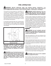
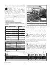
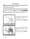
The rear spinners have been designed and tested to
provide the best spread pattern for most liquids and
semi solid manure. However, the pattern will vary for
each specific condition. The factors that contribute most
to differing patterns will be moisture content and the
amount and length of bedding material. For most typical
conditions, the spread pattern should be uniform and
about 15 ft. wide. When this is the case, plan your
spreading patterns so you donot have to travel over pre
-
viously spread manure which will be slippery, resulting
in poor traction. Traction on wet grass is also poor.
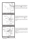
When the resulting pattern may require that you over
-
lap during spreading, use precautions on slopes and
hills where you could experience a loss of traction by
traveling over ground withpreviously spread manure.
NOTE: Further control of the application rate is possible
by the relationship of tractor engine speed to ground
speed (transmission gear selection). For optimum, trou
-
ble-free performance it is recommended to operate at or
near engine PTO speed.
When the spreader is empty, idle the tractor and stop
the PTO. Close the flow control rear gate.
WARNING: NEVER OPERATE PTO ABOVE
ITS NORMAL 540 or 1000 RPM RATING. TRAC-
TOR’S PTO MUST
MATCH IMPLEMENT PTO.
NOTE: Failure to idle the tractor before disengaging the
PTO will cause roller chain over-running and damage to
the chain tighteners.
NOTE: Maximum life of the PTO shaft universal joints
will result if you stop the PTO while making turns at the
end of the field.
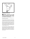
CAUTION: DO NOT EXCEED THE MAXIMUM
80° TURNING ANGLE ON THE CONSTANT VELOC
-
ITY PTO DRIVELINE. EXCEEDING THE TURNING
ANGLE WILL DAMAGE THE CONSTANT VELOCITY
“CENTER HOUSING” AND WILL EXERT EXCES
-
SIVE PRESSURES ON THE PTO INPUT CENTER
SHAFT AND RELATED BEARINGS.
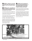
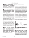
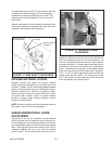
SHEAR SPROCKET INSTRUCTIONS
The Meyer Spreader you have received has been
equipped with a shear sprocket design on the main au
-
ger drive sprockets. The augers are being driven by two
allen head grade 8 bolts. The design is such that if the
bolts are sheared another set of holes to install new
shear bolts will always be accessible without turning
over the machine.
DANGER: AT NO TIME SHOULD
INSTALLATION BE DONE WITH ANYONE ON THE
TRACTOR. SHUT THE TRACTOR OFF, REMOVE
THE KEY AND DISCONNECT THE DRIVE LINE
BEFORE DOING ANY SERVICE ON THIS
MACHINE. SERIOUS INJURY OR DEATH MAY
OCCUR IF SAFETY IS NOT FOLLOWED.
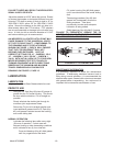
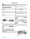
The plate sprocket is set up with the initial drive bolts be
-
ing 9/16” diameter (Prior to serial # SI088865/8720287),
5/8” diameter (Serial # SI088865/8720287 and later).
Install the new bolts in the proper way as to drive off of
THE HEAD of the bolt, not on the nut.
Part # Description
831-5618-1.75 9/16-20x1-3/4” Allen Head
Cap Bolt
831-5618-2.25 9/16-20x2-1/4” Allen Head
Cap Bolt
884-5618 9/16-20 Top Locknut Grade 8
831-6318-1.75 5/8-18x1-3/4” Allen Head
Cap Bolt
884-6318 5/8-18 Top Locknut Grade 8
910-0100 140B35 Shear Sprocket As
-
sembly Complete
Model 8720/8865 -13-