


– 14 –
b. Spider vane adjustments
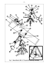
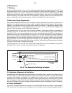
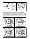
If the diagonal mirror (1, Fig. 8) is left or right of center within the drawtube (2, Fig. 8), loosen the spider vane
adjustment/lock knobs (1, Fig. 5) located on the outside surface of the main tube and slide the entire
diagonal assembly up or down the tube along the slotted holes, until the diagonal mirror is centered in the
drawtube.
If the diagonal mirror (1, Fig. 8) is above or below of center within the drawtube, thread in one of the spider
vane adjustment/ lock knobs while unthreading the other. Only make adjustments to 2 knobs at a time until
the diagonal mirror is in the drawtube. When the spider vane is correctly positioned, it will look like Fig. 9.
(Note that the diagonal mirror is misaligned.)
c. Diagonal holder adjustments
If the diagonal mirror (1, Fig. 9) is centered in the drawtube (2, Fig. 9), but the primary mirror is only partially
visible in the reflection (3, Fig. 9), the 3 Phillips-head diagonal tilt screws (2, Fig. 5) must be unthreaded
slightly to the point of where you can rotate the diagonal holder (3, Fig. 5) from side-to-side by grasping the
diagonal holder with your hand and rotating until you see the primary mirror become as centered in the
reflection of the diagonal mirror as possible. Once you are at the best position, thread in the 3 Phillips-head
diagonal tilt screws to lock the rotational position. Then, if necessary, make adjustments to these 3 Phillips-
head screws to refine the tilt-angle of the diagonal mirror until the entire primary mirror can be seen centered
within the diagonal mirror reflection. When the diagonal mirror is correctly aligned, it will look like Fig. 10.
(Note that the primary mirror is shown out of alignment.)
d. Primary mirror adjustments
If the diagonal mirror (1, Fig. 10) and the reflection of the primary mirror (2, Fig. 10) appear centered within
the drawtube (3, Fig. 10), but the reflection of your eye and the reflection of the diagonal mirror (4, Fig. 10)
appear off-center, you will need to adjust the primary mirror tilt Phillips-head screws of the primary mirror cell
(3, Fig. 6). These primary tilt screws are located behind the primary mirror, at the lower end of the main
tube. See Fig. 4. To adjust the primary mirror tilt screws, first unscrew several turns, the 3 hex-head primary
mirror cell locking screws (2, Fig.6) that are next to each primary mirror tilt Phillips-head screw. Then by trial-
and-error, turn the primary mirror tilt Phillips-head screws (3, Fig. 6) until you develop a feel for which way
to turn each screw to center the reflection of your eye. Once centered, as in Fig. 7, turn the 3 hex-head
primary mirror cell locking screws (2, Fig. 6) to relock the tilt-angle adjustment.
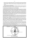
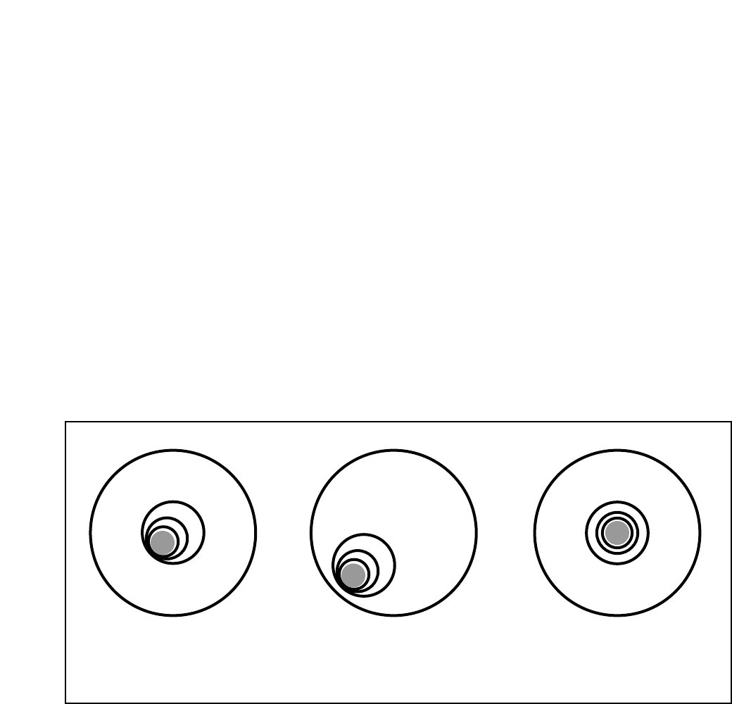
e. Star testing the collimation
With the collimation performed, you will want to test the accuracy of the alignment on a star. Use the
MA25mm eyepiece and point the telescope at a moderately bright (second or third magnitude) star, then
center the star image in the telescope’s field-of-view. With the star centered follow the method below:
• Bring the star image slowly out of focus until one or more rings are visible around the central disc. If the
collimation was performed correctly, the central star disk and rings will be concentric circles, with a dark
Fig. 11A Fig. 11B Fig. 11C