


– 13 –
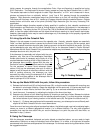
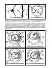
falls directly through the center of the focuser drawtube (17, Fig. 1). These mirror tilt adjustments are made
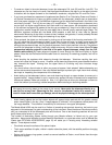
with the diagonal assembly (Fig. 5) and the primary mirror cell (Fig. 6), and will be discussed later.
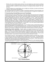
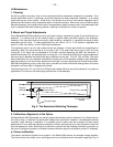
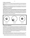
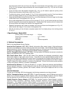
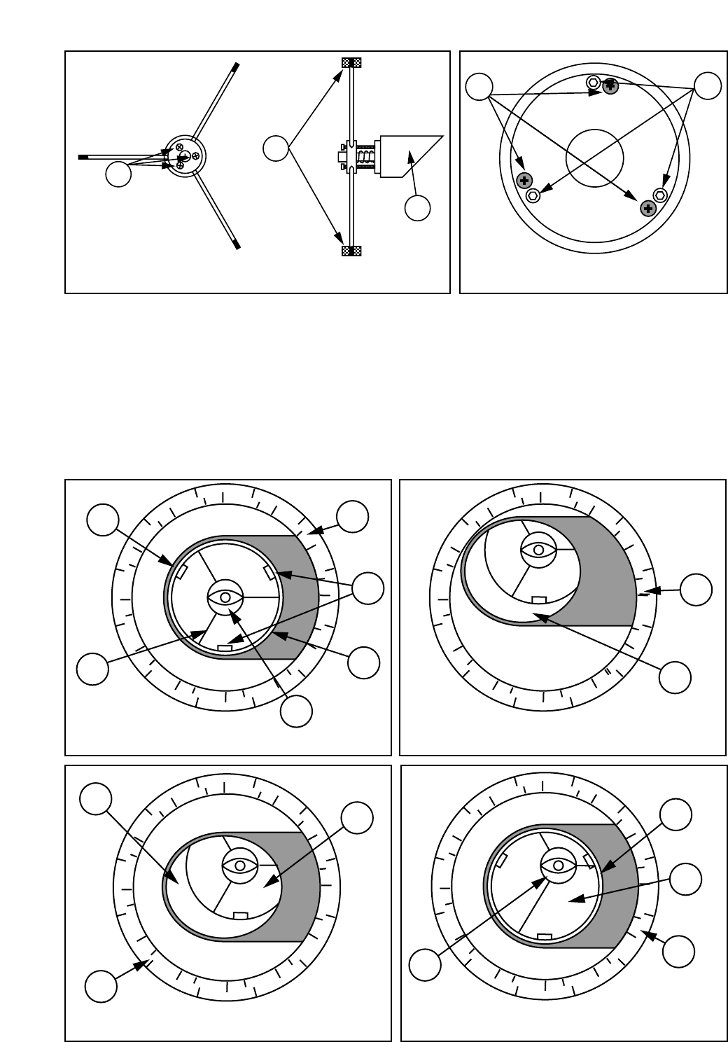
To inspect the view of the mirror collimation, look down the focuser drawtube with the eyepiece removed.
The edge of the focuser drawtube (1, Fig. 7), will frame the reflections of the primary mirror with the 3 mirror
clips (2, Fig. 7), the diagonal mirror (3, Fig. 7) , the spider vanes (4, Fig. 7), and your eye (5, Fig. 7). Properly
aligned, all of these reflections will appear concentric (i.e. centered) as illustrated in Figure 7. Any deviation
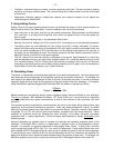
from the concentric reflections will require adjustments to the diagonal assembly (Fig. 5), and/or the primary
mirror cell (Fig. 6).
2
1
3
Fig. 5: Diagonal Assembly
3
2
Fig. 6: Primary Mirror Cell
4
5
3
3
1
2
2
2
2
2
1
3
4
1
1
Fig. 9: Diagonal Mirror Misalignment Fig. 10: Primary Mirror Misalignment
Fig. 7: Correct Collimation Fig. 8: Spider Vane Misalignment