


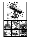
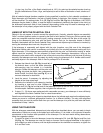


– 7 –
the counterweight lock (7, Fig. 1a) of the counterweight. Note: If the counterweight ever slips, the
secured threaded safety washer/screw (8, Fig. 1a) will not let the weight slide entirely off the
counterweight shaft. Be certain that this safety washer/screw is always in place.
7. Attach the flexible cables (4, Fig. 1a) and (3, Fig. 1a and 1e), as shown. These cables are secured in
place with a firm tightening of the thumbscrews located at the attachment ends of each cable.
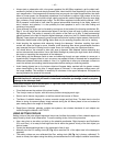
8. Tilt the polar axis (10, Fig. 1c) of the telescope to roughly a 45° angle with the horizon. This tilt is
accomplished by first loosening the latitude adjustment lock (11, Fig. 1a and 1e), adjusting the mount
and firmly re-tightening the latitude control lock.
9. Remove the optical tube attachment thumbscrews (14, Fig. 1d) from the optical tube mounting bolts
that are on the underside of the main optical tube (12, Fig. 1a). Then lay the telescope optical tube
assembly onto the saddle plate (13, Fig. 1a) passing the mounting bolts through the holes in the saddle
of the mount. Re-attach the attachment thumbscrews to the mounting bolts, and tighten to a firm feel.
See Fig. 1d.
10. Attach the viewfinder bracket (20, Fig. 1a) to the telescope using the 2 thumbscrews provided (16, Fig.
1a). The bracket fits over the two small bolts. Thread the thumbscrews over the bolts and tighten to a
firm feel. Slide the Viewfinder tube (24, Fig. 1a) into the bracket and loosely tighten the tube using the
Viewfinder adjustment screws. Remove the Viewfinder dustcover (9, Fig. 1a). See “Aligning the
Viewfinder” below.
11. Insert the 25mm eyepiece (13, Fig. 1) into the eyepiece holder (17, Fig. 1a). Secure the eyepiece in
place by tightening the eyepiece holder thumbscrews (18, Fig. 1a) to a firm feel.
The telescope is now completely assembled. Before it can be affectively used, however, the viewfinder (24,
Fig. 1a) must be aligned with the main telescope.
ALIGNING THE VIEWFINDER
The wide field of view provided by the 5 x 24mm viewfinder permits easy object sighting prior to
observation in the higher-power main telescope. The 5 x 24 Viewfinder (24, Fig. 1a) and viewfinder bracket
(20, Fig. 1a) attaches to the telescope tube assembly as described above. In order for the viewfinder to be
functional, however, it must be aligned to the main telescope, so that both the viewfinder and main
telescope point at the same position in the sky. With this simple alignment performed, finding objects is
greatly facilitated, since you will first locate an object in the wide-field viewfinder, then you will look in the
eyepiece of the main telescope for a detailed view. To align the viewfinder follow these steps:
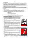
1. Remove the telescope front dust cover (39, Fig. 1), and the dust cover of the viewfinder (9, Fig. 1a).
2. Place the low- power (MA 25mm) eyepiece into the focuser of the main telescope.
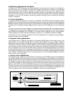
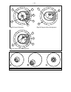
3. Unlock the Right Ascension (R.A.) lock (22, Fig. 1c) and the Declination (Dec.) lock (23, Fig. 1c) so
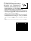
that the telescope turns freely on both axes. Then point the main telescope at some well-defined land
object (e.g. the top of a telephone pole) at least 200 yards distant, and re-lock the R.A and Dec. axes.
Turn the flexible cable controls, (4, Fig. 1a) and (3, Fig. 1a and 1e), to center the object in the
telescopic field.
4. With the front of the viewfinder already centered in the front bracket ring, look through the viewfinder
and loosen or tighten, as appropriate, one or more of the rear viewfinder bracket ring thumbscrews (26,
Fig. 1a) until the viewfinder’s crosshairs are likewise centered on the object previously centered in the
main telescope.
5. Check this alignment on a celestial object, such as a bright star or the Moon, and make any
refinements necessary, using the method outlined above.
With this alignment performed, objects first located in the wide-field viewfinder will also be centered in the
main telescope’s field of view. (Note: The viewfinder presents an image which is upside-down.)
BALANCING THE TELESCOPE
In order for the telescope to move smoothly on its mechanical axes, it must first be balanced as follows:
1. Loosen the R.A. lock (22, Fig. 1a). With the R.A. lock loosened, the telescope mount will turn freely
about the polar axis (10, Fig. 1c). Rotate the telescope about the polar axis so that the counterweight
shaft (6, Fig. 1a) is parallel to the ground (horizontal).