


– 13 –
d. Star testing the collimation
With the collimation performed, you will want to test the accuracy of the
alignment on a star. Use the MA 25mm eyepiece and point the telescope at
a moderately bright (second or third magnitude) star, then center the star
image in the telescope’s field-of-view. With the star centered follow the
method below:
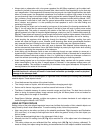
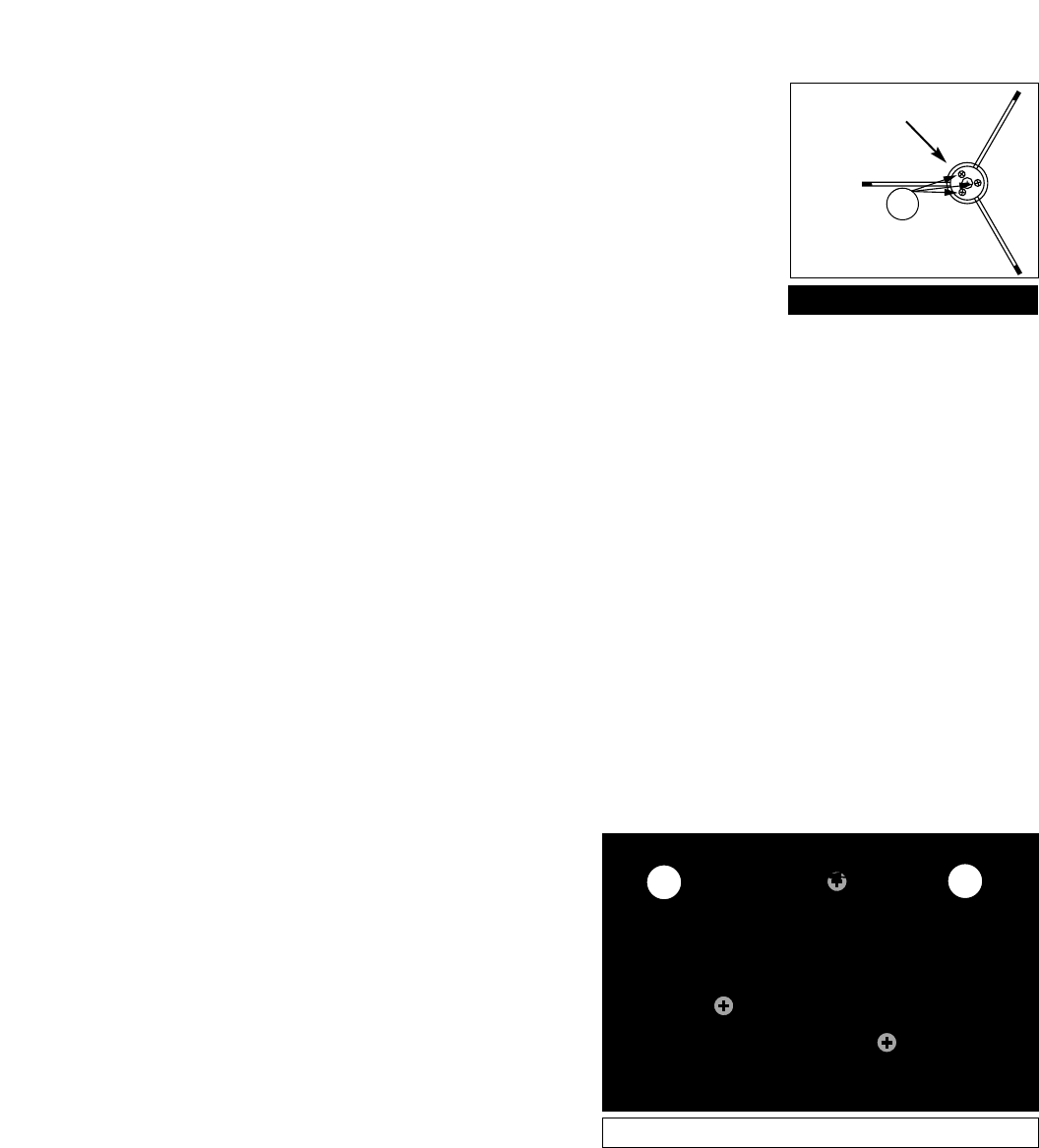
• Bring the star image slowly out of focus until one or more rings are
visible around the central disc. If the collimation was performed correctly,
the central star disk and rings will be concentric circles, with a dark spot
dead center within the out-of-focus star disk (this is the shadow of the
secondary mirror), as shown in Fig. 12C. (An improperly aligned
telescope will reveal elongated circles (Fig. 12A), with an off-center dark shadow.)
• If the out-of-focus star disk appears elongated (Fig. 12A), you will need to adjust the primary mirror
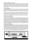
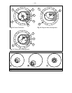
Phillips-head tilt screws of the primary mirror cell (3, Fig. 8).
• To adjust the primary mirror tilt screws (3, Fig. 8), first unscrew several turns the 3 hex-head primary
mirror cell locking screws (2, Fig. 8), to allow free turning movement of the tilt knobs.
• Using the flexible cable controls (3, Fig. 1e and 4, Fig. 1a), move the telescope until the star image is
at the edge of the field-of-view in the eyepiece, as in Fig. 12B.
• As you make adjustments to the primary mirror tilt screws (3, Fig. 8), you will notice that the out-of-
focus star disk image will move across the eyepiece field. Choose one of the 3 primary mirror tilt
screws and slightly move the shadow to the center of the disk. Then slightly move the telescope using
the flexible cable controls to center the star disk image in the center of the eyepiece.
• If any further adjustments are necessary, repeat this process as many times as needed until the out-
of-focus star disk appears as in Fig. 12C, when the star disk image is in the center of the eyepiece
field.
• With the star testing of the collimation complete, tighten the 3 hex-head primary mirror locking screws
(2, Fig. 8).
2
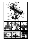
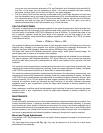
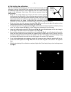
Fig. 7: Diagonal Assembly.
3
2
Fig. 8: Primary Mirror Cell.
1
Remove
adhesive
backing