


– 12 –
Collimation (Alignment) of the Optics
All Meade 114ST EQ-D telescopes are optically aligned at the factory prior to shipment. It is unlikely that
you will need to align, or collimate, the optics after receipt of the instrument. However, if the telescope
received unusually rough handling in shipment, it is possible that the optics must be re aligned for best
optical performance. In any case this alignment procedure is simple, and requires only a few minutes the
very first time the telescope is used. Take the time to familiarize yourself with the following collimation
procedure, so that you will recognize a properly collimated instrument and can adjust the collimation
yourself, if necessary.
a. Correct collimation
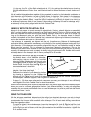
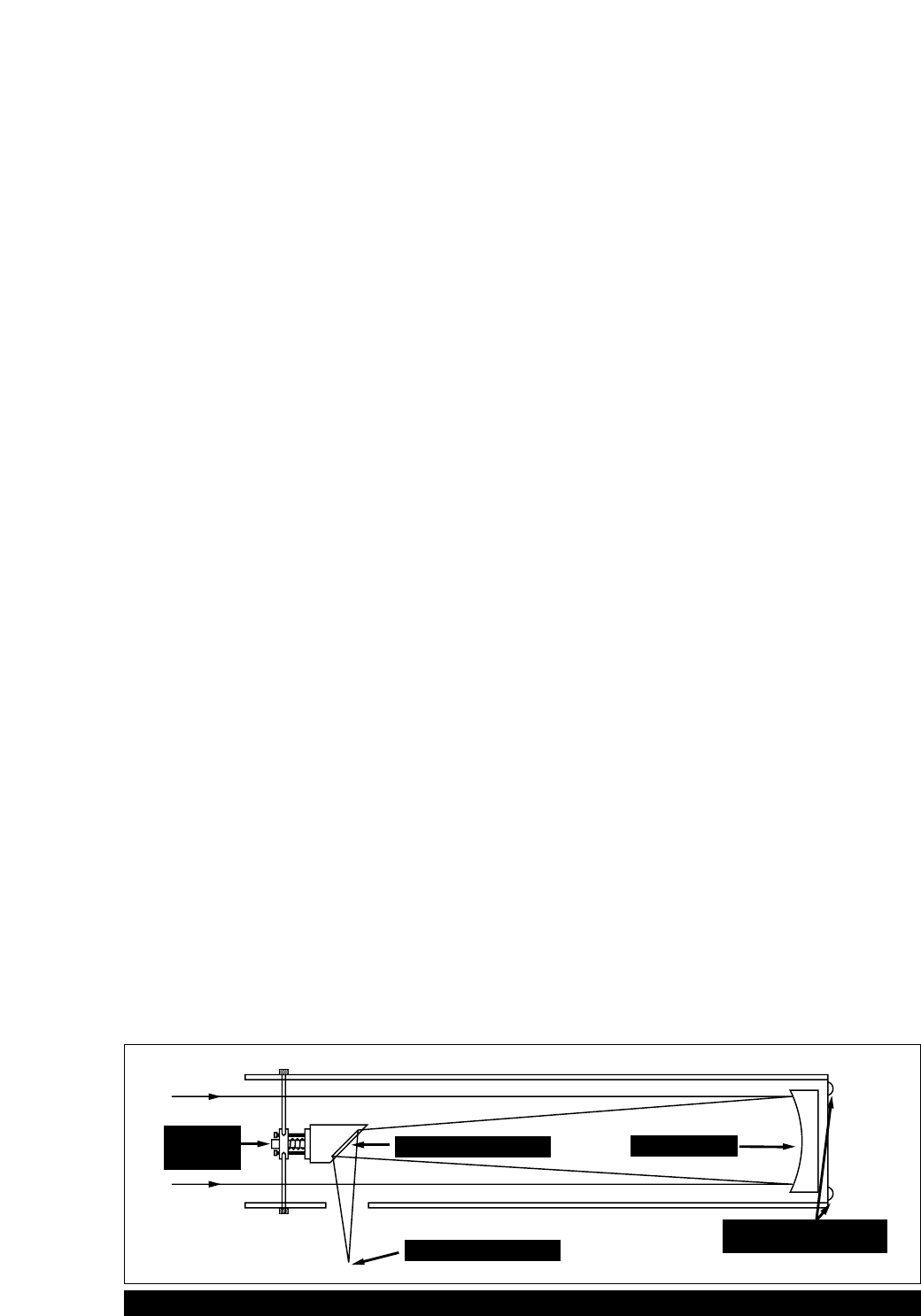
The properly collimated (aligned) mirror system in the Meade 114ST EQ-D assures the sharpest images
possible. This occurs when the primary mirror and diagonal mirror are tilted so that the focused image (see
Fig. 6) falls directly through the center of the focuser drawtube (17, Fig. 1a). These mirror tilt adjustments
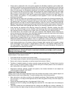
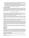
are made with the diagonal assembly (Fig. 7) and the primary mirror cell (Fig. 8), and will be discussed
later.
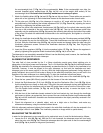
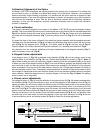
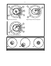
To inspect the view of the mirror collimation, look down the focuser drawtube with the eyepiece removed.
The edge of the focuser drawtube (1, Fig. 9), will frame the reflections of the primary mirror with the 3 mirror
clips (2, Fig. 9), the diagonal mirror (3, Fig. 9) , the spider vanes (4, Fig. 9), and your eye (5, Fig. 9).
Properly aligned, all of these reflections will appear concentric (i.e., centered) as illustrated in Fig. 9.
Any deviation from the concentric reflections will require adjustments to the diagonal assembly (Fig. 7),
and/or the primary mirror cell (Fig. 8).
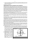
b. Diagonal holder adjustments
If the diagonal mirror (1, Fig. 10) is centered in the drawtube (2, Fig. 10), but the primary mirror is only
partially visible in the reflection (3, Fig. 10), the 3 Phillips-head diagonal tilt screws (1, Fig. 7). Note: To
adjust these screws you must first remove an adhesive backing) must be unthreaded slightly to the point
of where you can tilt the diagonal holder (3, Fig. 7) from side-to-side by grasping the diagonal holder with
your hand and tilt until you see the primary mirror become as centered in the reflection of the diagonal
mirror as possible. Once you are at the best position, thread in the 3 Phillips-head diagonal tilt screws to
lock the rotational position. Then, if necessary, make adjustments to these 3 Phillips-head screws to refine
the tilt-angle of the diagonal mirror until the entire primary mirror can be seen centered within the diagonal
mirror reflection. When the diagonal mirror is correctly aligned, it will look like Fig. 10. (Note: The primary
mirror is shown out of alignment.)
c. Primary mirror adjustments
If the diagonal mirror (1, Fig. 11) and the reflection of the primary mirror (2, Fig. 11) appear centered within
the drawtube (3, Fig. 11), but the reflection of your eye and the reflection of the diagonal mirror (4, Fig. 11)
appear off-center, you will need to adjust the primary mirror tilt Phillips-head screws of the primary mirror
cell (3, Fig. 11). These primary tilt screws are located behind the primary mirror, at the lower end of the
main tube. See Fig. 6. To adjust the primary mirror tilt screws, first unscrew several turns, the 3 hex-head
primary mirror cell locking screws (2, Fig. 8) that are next to each primary mirror tilt Phillips-head screw.
Then by trial-and-error, turn the primary mirror tilt Phillips-head screws (3, Fig. 8) until you develop a feel
for which way to turn each screw to center the reflection of your eye. Once centered, as in Fig. 9, turn the
3 hex-head primary mirror cell locking screws (2, Fig. 8) to relock the tilt-angle adjustment.
Monture
Diagonale
Miroir Diagonal
Image Focalisée
Miroir Primaire
Vis D'inclinaison
du Miroir Primaire
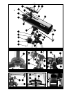
Fig. 6: The Newtonian Reflecting Telescope.
Diagonal
Assembly
Diagonal Mirror
Focused Image
Primary Mirror
Primary Mirror-Tilt
Screws