


36
41
16
27
37
38
39
26
23
36
35
34
17
19
19
15
13
9
11
20
10
2
6
7
7
29
6
2
6
7
7
6
5
1
3
2
30
28
4
42
1
3
2
30
43
14
14
32
43
44
31
12
38
38
4
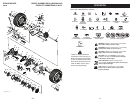
LRV-B_Steering_3
32
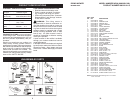
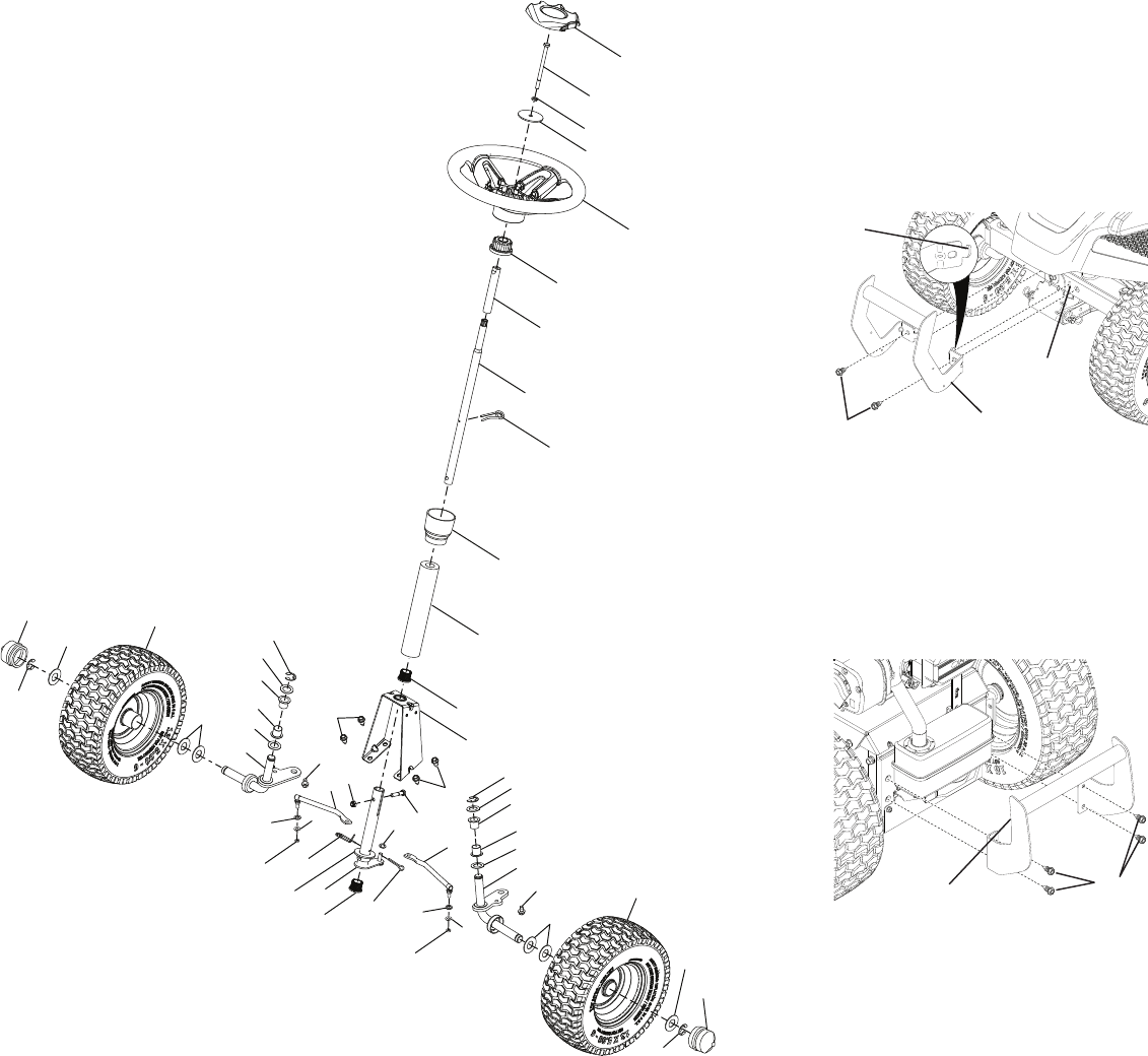
RIDING MOWER MODEL NUMBER MC30 (96022001300)
STEERING
PRODUCT NUMBER 960 22 00-13
9
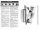
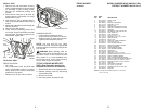
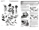
TO ATTACH FRONT BUMPER
NOTE: For ease of assembly, you may wish
to obtain the assistance of another person
for mounting bumper to riding mower.
1. Remove (2) screws from front chassis of
riding mower.
2. Tilt the front bumper so that the bumper
tabs catch the slots on the front of the
chassis and lower the bumper in to place.
3. Attach the bumper to front of chassis with
screws removed in step 1.
4. Tighten the two (2) screws se cure ly.
TO ATTACH REAR BUMPER
NOTE: For ease of assembly, you may wish
to obtain the assistance of another person
for mounting bumper to riding mower.
1. Remove (4) screws from rear chassis of
riding mower.
2. Position bumper as shown and assemble
to rear chassis with screws removed in
step 1.
3. Tighten the four (4) screws se cure ly.
Screw
Rear Bumper
Front Bumper
Screw
Tab
Slot
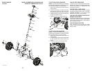
CHECK TIRE PRESSURE
The tires on your riding mower were overin-
flated at the factory for shipping purposes.
Correct tire pressure is important for best
cutting performance.
CHECK DECK LEVELNESS
For best cutting results, mower housing
should be properly leveled. See “TO LEVEL
MOWER HOUSING” in the Service and
Adjustments section of this manual.
CHECK FOR PROPER POSITON OF
MOWER DRIVE BELT
See the figure that is shown for replacing the
mower drive belt in the service and adjust-
ment section of this manual. Verify that the
belt is routed correctly.
CHECK BRAKE SYSTEM
After you learn how to operate your riding
mower, check to see that the brake is oper-
ating properly.