


8
NOTE: You may now roll your riding
mower off the skid. Follow the ap pro pri ate
instruction below to remove the riding mower
from the skid.
WARNING: Before starting, read, un-
der stand and follow all in struc tions in the
Operation section of this manual. Be sure
riding mower is in a well-ventilated area.
Be sure the area in front of riding mower is
clear of other people and objects.
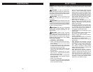
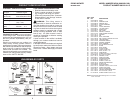
TO ROLL RIDING MOWER OFF
SKID (See Op er a tion section for
location and function of con trols)
1. Raise deck lift lever to its highest position.
2. Release parking brake by depressing
clutch/brake ped al.
3. Shift unit to neutral.
4. Roll riding mower forward off skid.
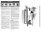
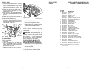
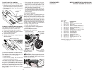
Adjustment Lever
Lumbar
Adjustment Knob
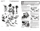
TO ADJUST SEAT
FRONT AND BACK -
• Sit in seat.
• Lift up adjustment lever and slide seat
until a comfortable position is reached
which allows you to press clutch/brake
pedal all the way down.
• Release lever to lock seat in position.
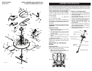
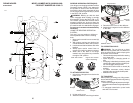
INSTALL SEAT
1. Remove bolt and flat washer se cur ing
seat to cardboard packing and set aside
for as sem bly of seat to riding mower.
Remove the cardboard packing and
discard.
2. Place seat on seat pan so all three (3)
bottom pads are positioned over large
slotted holes in pan.
3. Push down on seat to engage pads in
slots and pull seat towards rear of riding
mower.
4. Raise seat and tighten bolt and large flat
washer securely.
5. Remove tape and discard.
6. Lower seat into operating position and
sit on seat. Press clutch/brake pedal all
the way down. If operating position is not
comfortable, adjust seat.
Adjustment
handle
Bolt
Flat
washer
Seat
pan
Pad
Tape
Slot
Tab
LUMBAR SUPPORT -
• Loosen lumbar adjustment knob.
• Slide seat back up or down to most com-
fortable position for lower back support.
• Tighten lumbar adjustment knob.
37
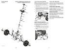
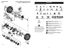
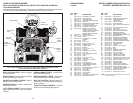
1 532 44 20-64 WHEEL TUBE
2 812 00 00-01 E-CLIP
3 532 18 89-67 WASHER, HARDENED
4 532 12 17-49 WASHER, 1/4 X 3/4
5 532 43 61-81 SPINDLE, RH
6 532 12 49-31 WASHER, HARDENED THRUST
7 532 12 49-37 BUSHING, STEERING COLUMN
9 819 13 14-14 WASHER
10 532 42 80-57 WELDMENT, LWR STRG SHAFT
11 532 43 61-83 LINK, STRNG LH
12 532 43 61-84 LINK, STRNG RH
13 874 78 05-24 BOLT, 5/16-18 X 1 1/2
14 819 11 12-16 WASHER 11/32 X 3/4 X 16 GA
16 532 43 62-82 BUSHING SNAP
15 873 80 05-00 NUT, 5/16-18
17 532 43 61-78 SUPPORT, UPPER STEERING
19 817 00 05-12 BOLT, 5/16-18 X 3/4
20 532 42 80-45 CLIP, RETAINER SPRING
23 532 43 77-47 ADAPTER, STEERING WHEEL
26 532 42 45-51 WHEEL, STEERING
27 532 44 15-06 CAP, STEERING WHEEL
28 532 19 98-49 CLIP, RETAINER SPRING
29 532 43 61-80 SPINDLE LH
30 532 19 32-68 CAP, HUB, AXLE
31 819 34 32-10 WASHER 1-1/16 X 2 X 10GA.
32 817 58 05-20 SCREW HEXWSH THD 5/16-18 X 1-3/4
34 532 43 61-82 SHAFT STEERING UPPER
35 532 44 20-66 BOOT LOWER STEERING WHEEL
36 532 19 60-75 SHAFT EXTENSION STEERING SPLINE
37 874 78 05-80 BOLT FIN HEX 5/16-18 UNC X 5 GR5
38 810 04 05-00 WASHER LOCK HVY HLCL SPR 5/16
39 819 11 38-12 WASHER
41 532 43 65-90 FOAM SHAFT STEERING
42 532 42 10-76 PIN, 5/64 X 3/4 COTTER
43 873 54 05-00 CROWNLOCK NUT 5/16-24 UNF
44 532 42 80-44 BUSHING
KEY PART
NO. NO. DESCRIPTION
NOTE: All component dimensions given in U.S. inches
1 inch = 25.4 mm
RIDING MOWER MODEL NUMBER MC30 (96022001300)
STEERING
PRODUCT NUMBER 960 22 00-13