


WARNING • DANGER
REMOVE TINES BEFORE STARTING ENGINE
AND MAKING ADJUSTMENTS.
8
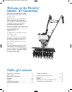
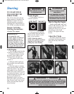
How to Assemble
Kickstand, Upper
Handles and
Carrying Handle
NOTE: If your Mantis
®
XP
was supplied with a
kickstand, please start at
line 1. If not, please start
with the assembly of the
carry handle in line 3 below.
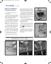
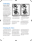
1. Locate the kickstand top
bracket (#70). Note that the
distance between the channels
is narrower on one end of the
bracket than the other. Place
the kickstand top bracket onto
the kickstand assembly (#69)
so the end where the channels
are closer together points
away from the foot of the
kickstand (Picture 1). Align
the bolt holes and insert two
3/8” bolts through the holes in
the top bracket and screw
them into the bottom bracket
by hand.
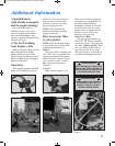
2. Lightly squeeze the
lower handles (#6) toward one
another so they line up with
the channels in the top bracket
of the kickstand and slide the
assembly down the lower
handles until the foot of the
kickstand is about 2" from the
ends of the lower handles
(Picture 2).
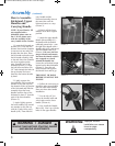
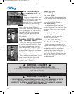
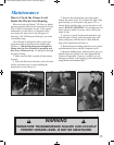
3. Again, lightly squeeze
the lower handles (#6) toward
one another so they line up
with the 2 holes in the carry
handle (#42). Then slide the
carry handle and the
kickstand assembly down at
the same time until the
kickstand comes to a stop
(Picture 3).
4. Gently pull the lower
handles out to their original
position.
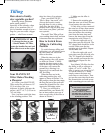
5. Attach the upper handle
throttle side assembly (#1) –
the handle with the throttle
cable and ground wire – onto
the right lower handle with a
shoulder bolt (#52), and secure
with the handle knob (#53).
(Picture 4
) Be sure you have
proper throttle movements
and that the throttle cable is
not wrapped or twisted
around the handle bar.
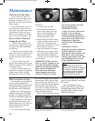
Locate the red lockout button
located on the throttle handle
(Picture 5). Press the red
lockout button and squeeze
the throttle lever and let go.
THIS MUST BE DONE
BEFORE STARTING THE
ENGINE.
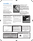
6. Follow the same steps to
install the other upper handle
onto the other lower handle.
Does not show other handle
installation.
7. Use the clip (#13) to
secure the throttle cable and
wire in place on the lower
handle. (Picture 6)
8. Now install the Handle
Brace (#8). Line it up with the
holes on the upper handles.
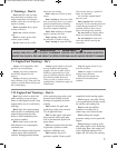
!
!
Picture 1 Picture 2
Picture 3 Picture 4
Picture 5 Picture 6
Assembly (continued)
WARNING:
Improper throttle
installation can cause
tines to rotate
unexpectedly.
!
401764 XP Tiller-Cultivator_manual 5/18/10 10:51 AM Page 8