


P 8/ 8
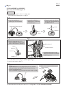
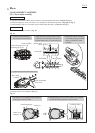
Fig. D-6
Fig. D-5
Switch
Fix Controller´s Lead wires
(red, black) in this Lead
wire holder.
Connect Receptacles to the Switch with facing the wire
connecting portion to the Housing set (L) side in order
to put the Lead wires on the Housing set (L).
Connect Receptacles to the Terminal with facing
the wire connecting portion to Housing set (L) side.
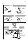
Adhesive
Pass the Lead wires of
LED circuit between
the Ribs.
LED circuit
In case Line filter has to
be used, put Line filter
into the space designated
with gray color.
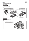
Controller
Controller
Housing set
(L) side
Housing set
(L) side
DC motor
Switch
Terminal
Fix all of the Lead wires
of Controller in this
Lead wire holder.
from Plus pole
of Terminal
from Controller
Terminal
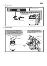
Wiring diagram (cont.)
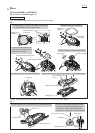
Fig. D-3 Fig. D-4
Controller
Controller has to be put into Housing set (L).
Note: Bring the Lead wire (blue) connecting portion to the bottom
side (Helical gear 47 side) and the wires connecting portions
to the front side (protector side).
Line filter
Wind Controller´s Lead wires (blue, white)
one time around Line filter.
To Plus pole of DC Motor
To Minus pole
of DC Motor
Lead wire (blue)
Front side
(Protector side)
Bottom side (Helical gear 47 side)
Housing set (L)
DC Motor