


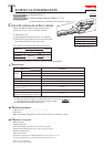

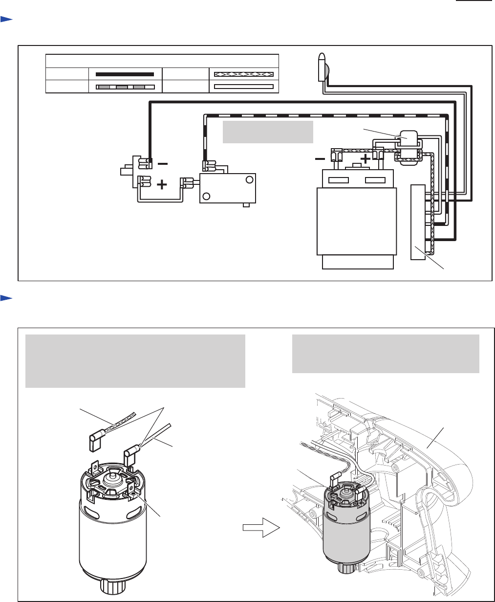
Circuit diagram
P 7/ 8
Fig. D-1
White
Color index of lead wires' sheath
Black
Red
Blue
LED
(Warning lamp for battery)
DC Motor
Controller
Line filter
Switch
Terminal
Line filter is not used
for some countries.
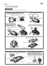
Wiring diagram
Fig. D-2
1. Find Terminal marked with Red dot marking.
2. Now connect the Lead wire (white) receptacle to
the Terminal with Red dot marking and the Lead
wire (blue) receptacle to the another Terminal.
Lead wire
(blue)
Red dot marking
Wire connecting portion of
Receptacles
Lead wire
(white)
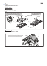
Housing set (L)
3. DC motor can be mounted with facing
the wire connecting portions of Receptacles
to Housing set (L) side.