


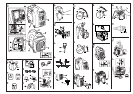
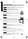
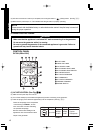
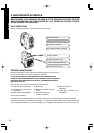
2. COMPONENTS (See Fig.
11
)
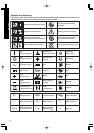
3.
CONTROLS AND INDICATORS
(See Fig.
22
)
1. ENGINE SWITCH (See Fig.
22
-
qq
)
Please refer to the illustrations on the back
page of
the front cover or back cover for
Fig.
11
to
66
indicated in the sentence.
NOTE
q RECOIL STARTER (HANDLE)
w CONTROL PANEL
e SIDE PANEL (L)
r AIR CLEANER
t FUEL DRAIN SCREW
y CARRYING HANDLE
u TANK CAP COVER
i EXHAUST OUTLET
o OIL DRAIN PLUG
!0 SIDE PANEL (R)
!1 OIL GAUGE (OIL FILLER)
!2 SPARK PLUG CAP
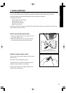
The engine switch is designed for easy operation
with the interlocking mechanism between the fuel
cock and the choke furnished.
When the engine stops due to oil shortage, it can
not be started anymore even by pulling the start
knob (just the alarm lamp flickers). In such a case,
replenish engine oil up to the mouth of the oil filling
port.
(Refer to page 6 for details about the oil
replenishing procedure).
The AUTO POWER SAVE LAMP is turned on when
the switch is in the “ON” position.
With the switch in the “ ” marking position, the
engine speed is reduced automatically when no
electricity is taken out, while the engine speed is
automatically adjusted in accordance with the load
condition when the electricity is taken out.
When using in the heavy load condition, set the
switch into the “ ” marking position to maintain
the electric power level in the stable condition.
When using DC power, turn the switch into the
“OFF” position.
5
ENGLISHFRANÇAISEESPAÑOL
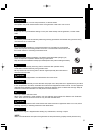
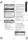
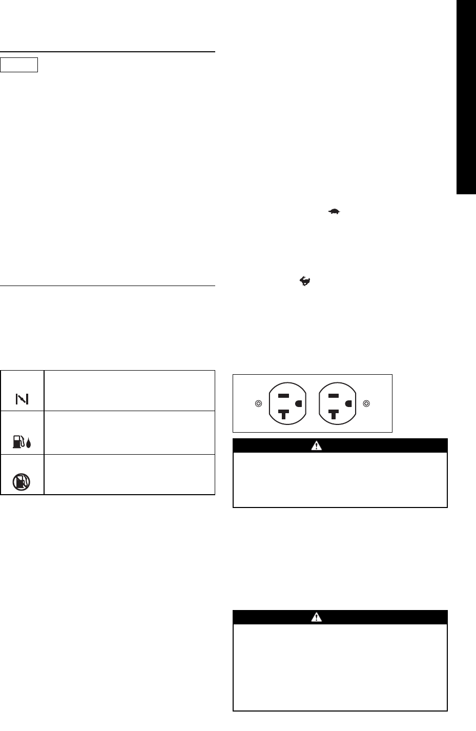
5. AC RECEPTACLES
AC electric power is available through this receptacle.
Use a ground type, three-leg plug as shown.
CHOKE
To start the engine, turn the knob to the
position. (Choke valve is closed.)
RUN
Keep the knob in this position after the
engine starts. (The engine can be
started with the knob at this position
when the engine is warm.)
STOP
To stop the engine, return the knob to
the position.
(The fuel cock is closed as well.)
Do not plug more than two appliances
into the generator at a time.
Do not put foreign objects into the plug
receptacle.
CAUTION
6. AC CIRCUIT BREAKER
AC circuit breaker will cut off electric current when
the current exceeds its limit or a malfunction occurs
in the connected appliances.
Check for excessive current consumption or defects
in the appliances. After making sure everything is in
order, push the circuit breaker button.
If circuit breaker continues to be activated,
discontinue use and check generator
and/or appliance for
malfunction with
their respective service representatives.
Never interfere with the operation of the
circuit breaker knob or keep pushing it in
the "ON" position.
CAUTION
2. PILOT LAMP and OVERLOAD LAMP
(See Fig.
22
-
ww
)
These lamps are turned on in the following conditions;
PILOT LAMP (Green) --- The lamp is turned on
while generating properly.
OVERLOAD LAMP (Red) --- The lamp is turned on in the
overload condition.
* The breaker will be activated after the lamp is
turned on for 20 seconds in the 120% electric
power condition, and results in no load condition.
* If the lamp is turned on, stop and start the engine
again to resume the operation.
3. OIL SENSOR LAMP (See Fig.
22
-
ee
)
When the level of the engine oil falls below the
prescribed value, the alarm lamp lights up and the
engine stops automatically.
4.
AUTO POWER SAVE SWITCH AND LAMP
(See Fig.
22
-
rr
)