


6
ENGLISHFRANÇAISEESPAÑOL
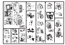
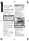
4. PRE-OPERATION CHECKS
(See Fig.
33
)
1. CHECK ENGINE OIL (See Fig.
33
-
qq
,
ww
)
Before checking or refilling oil, be sure generator is
located on stable and level surface with engine stopped.
Remove oil filler cap and check the engine oil level.
If oil level is below the lower level line, refill
with suitable oil (see table) to upper level line.
Do not screw in the oil filler cap when
checking oil level.
Change oil if contaminated.
(See "How-To" Maintenance.)
Oil capacity . . . . 0.4 liters (0.42 qts)
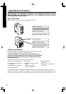
2. CHECK ENGINE FUEL (SeeFig.
22
-
oo
,
33
-
ee
)
If fuel level is low, refill with unleaded
automotive gasoline.
Fuel level should never over the RED marking
at the inlet portion. (SeeFig.
33
-
ee
-q
)
q RED MARKING
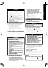
Be sure to use the fuel filter screen on the fuel
filter neck.
q FUEL TANK CAP
w FUEL FILTER SCREEN
e TANK CAP COVER
Fuel tank capacity . . . 3.5 liters (0.92 US.gal)
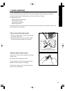
When using the generator first time or stopping
due the fuel running out, pull the recoil handle
several times after filling fuel up to the RED
marking at the inlet portion of the fuel tank.
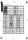
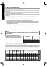
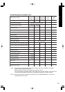
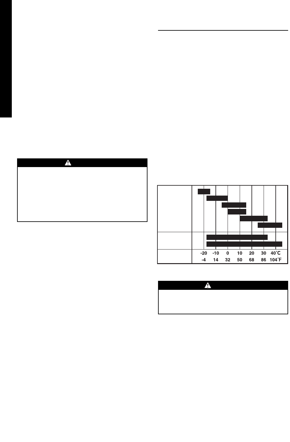
Recommended engine oil:
Use 4-stroke automotive detergent oil of API service class
SE or higher grade (SG, SH or SJ is recommended).
SAE 10W-30 or 10W-40 is recommended for
general, all-temperature use. If single viscosity oil is
used, select the appropriate viscosity for the
average temperature in your area.
Ambient
temperature
Single grade
Multigrade
5W
10W
20W
#20
#30
#40
10W
-
30
10W
-
40
Do not refuel while smoking or near open
flame or other such potential fire hazards.
Otherwise fire accident may occur.
WARNING
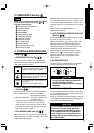
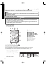
8. DC CIRCUIT BREAKER (See Fig.
22
-
yy
)
DC circuit breakers shut off electric current when
the current exceeds its limit or a malfunction occurs
in the connected appliance.
Check for excessive current consumption or defects
in the appliance. After making sure everything is in
order, push the button to the " ON " position.
q BUTTON e IN (ON)
w KNOB r OUT (OFF)
7. DC TERMINALS (See Fig.
22
-
tt
)
DC electric power for battery charge is available.
- Red is positive (+) terminal.
- Black is negative (
-
) terminal.
10. RECOIL STARTER (See Fig.
22
-
uu
)
Pull this handle to start the generator.
q RECOIL STARTER HANDLE
q FUEL TANK CAP
w FUEL FILTER SCREEN
e TANK CAP COVER
9. GROUND TERMINAL (See Fig.
22
-
ii
)
Terminal for grounding the generator.
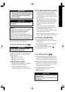
12. SIDE COVER ( . .) (See Fig.
22
-
!!00
)
To access the following items for servicing, take the
applicable side cover out by removing the screw
with screwdriver or coin.
LH-side cover ---- Air cleaner etc.
RH-side cover ---- Oil level gauge, Ignition coil,
Spark plug etc.
11
. FUEL TANK CAP (See Fig.
22
-
oo
)
The fuel tank cap is located behind the cover.
To open the cover, lift up with the dent portion
depressed backward as shown in the illustration.
Remove the fuel tank cap by turning
counterclockwise.
If circuit breaker continues to be activated,
discontinue use and check generator
and/or appliance for
malfunction with
their respective service representatives.
Never interfere with the operation of the
circuit breaker knob or keep pushing it in
the "ON" position.
CAUTION