


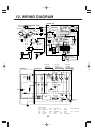
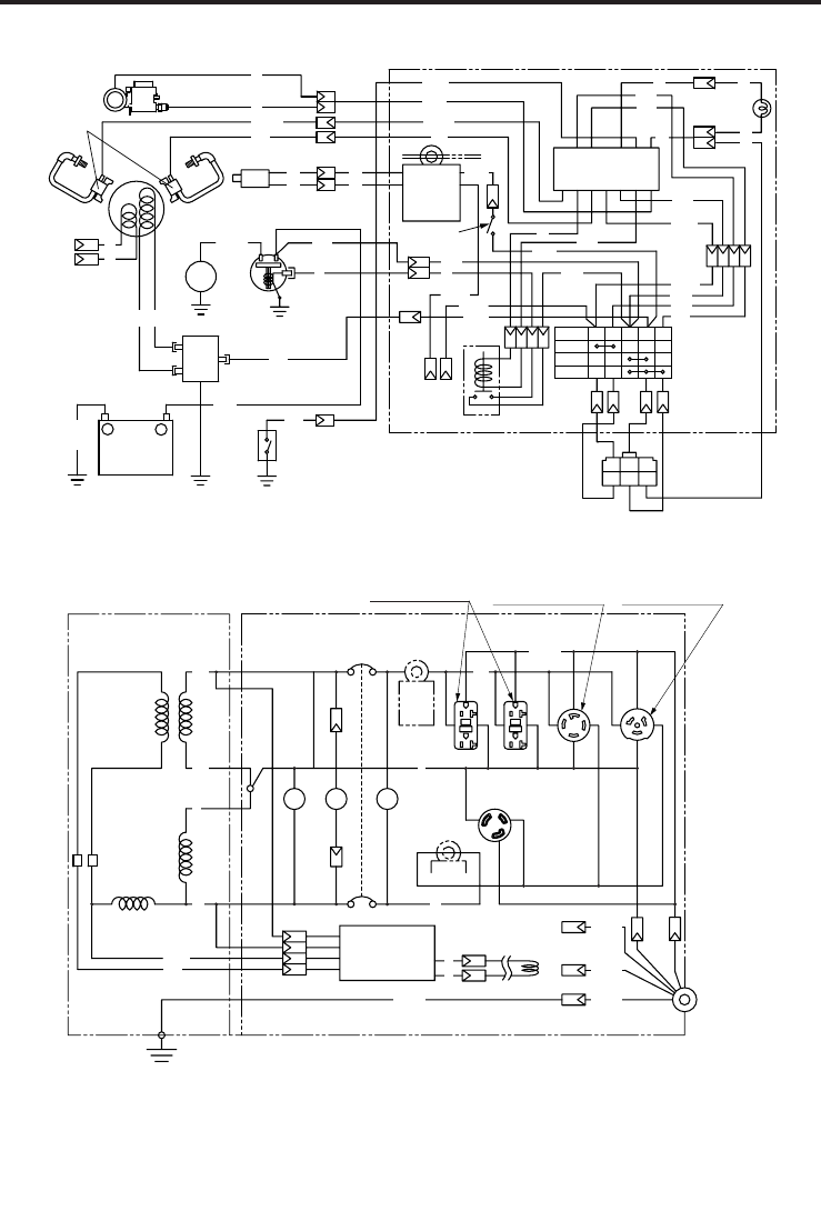
12. WIRING DIAGRAM
32
Blk/Y
53
2
4
(AC output)
(
AVR
)
1
CONTROL BOX
Fuel cut
Ignition coil
Auto choke
(
Bimetal
)
Electric
starter
Oil pressure
switch
Regulator
Magnetic
switch
Charge
coil
Exciting
coil
-
+
Battery 12V
Grn/Y
Grn
LBlu
Gry W
Key
switch
to earth
terminal
ST Relay
Connector
(
Remote control
)
Gry
R15
Blk15
Grn
WW
W
Blk/W
Gry
Gry
Blk
R
Blk/W
Blk
R
Grn/Y
Grn/Y
Grn
Grn
Org
R
Org
Org
LBlu
LBlu
LBlu
Brn
Y
Org
R
W
W
W
W
W
W
W
OFF
-
M+MB
L
.
IG
ST
ON
START
R/W
Idle
solenoid
1
Electronic control unit
2
13
3
12
4
11
5
10
6
987
Blk
Y
Y
Blk
Grn/Y
Grn/Y
Idle control
switch
Idle
control
unit
Oil pressure
warning lamp
(
Red
)
LGrn
Org
Blk
Blu
Blk
R
R
W W
LGrn
Grn/Y Grn/Y
Grn/Y
Brn
CONTROL BOXGENERATOR
Y
Y
No-fuse breaker
Voltmeter
Pilot lamp
VHr
PL
Earth(Ground)
terminal
Field
Winding
AC Winding 1AC Winding 2
AVR
w w
Idle
control
unit
AC otuput
receptacle(120V)
REC2
AC output
receptacle
(120V) REC1
AC output
receptacle
(120/240V) REC3
AC output
receptacle
(120/240V) REC4
BrushBrush
Auxiliary Winding
Exciting coil
(Engine)
Auto idle unit
to Key switch
Grn/Y
Grn/Y
Wiring color cord
LGrn
R/W
Blk/RBlk Black Brn/W Brown/White R Red
Blk/W Black/White Grn Green W White
Blu Blue Grn/W Green/White Y Yellow
LBlu Light blue Org Orange Pik Pink
Brn Brown Gry Gray Grn/Y Green/Yellow
Light green
Red/White
Black/Red