


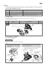
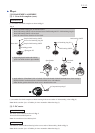
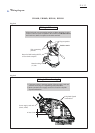
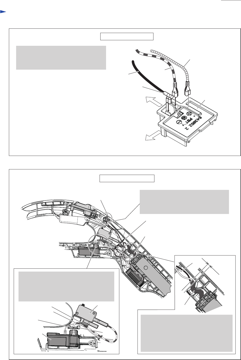
While facing the wire connecting portion
to Pipe 25 side, connect the Lead wire
(black) to Terminal. And then, connect Lead
wires (red, yellow) to Terminal.
Fig. D-7
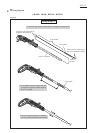
Fig. D-8
Wiring to Terminal
Wiring in Handle (L)
Pipe 25 side
Terminal
Handle (L) side
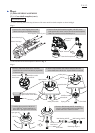
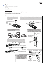
Pass Lead wires (red, yellow) between Terminal
and Switch through the space between Rib A
and Rib B.
Pass Lead wire (yellow) through the space
between Rib A and Rib C.
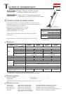
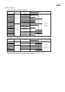
UR141D, UR181D
Rib A
Rib C
Terminal
Switch
Rib B
Lead wire (red)
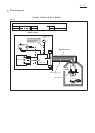
Wiring diagram
P 12/ 12
Wire connecting portion
Lead wire
(black)
Lead wire
(Yellow)
Lead wire
(red)
Rib
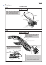
Power supply cord unit
LED warning lamp
Rib
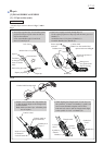
1. Come out at least 5 mm long portion of
Power supply cord unit from the lower
edge of Labyrinth figured lead holders.
But the sheath end must not go over Rib A.
2. Make sure that Power supply cord unit is
fixed in Labyrinth figured lead holders.
at least
5 mm
Sheath
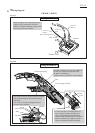
Put LED warning lamp’s lead wire (red)* on
its lead wire (black) and insert them into
the groove in Handle (L).
*using Lead wire (white) for some countries