


[3] DISASSEMBLY/ASSEMBLY
[3] -3. Pipe section (cont.)
ASSEMBLING
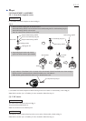
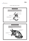
Assemble Pipe section as drawn in Figs. 7 and 8.
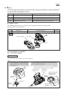
Fig. 7
Symbol of
“Unlock”
Triangle mark
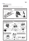
Fig. 8
Left
Right
Pipe cap
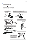
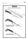
1. Insert Pipe cap into Pipe 25 so that the square
projection of Pipe cap fits in the left side of
Pipe as drawn below.
Next, mount Rubber pipe 25 and Lock
sleeve 25 onto Pipe 25.
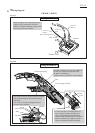
2. Pass Power supply cord unit through Pipe 25.
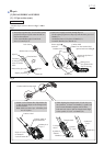
Fit the square projection of Pipe cap into the inner groove of
Handle (L).
Set Rubber sleeve 25 in place of Handle (L).
Assemble Handle (R) to Handle (L).
Square projection
Two holes
on the pipe end
close to caution
label
Hole on the pipe end
Rubber sleeve 25
Lock sleeve
Pipe 25
Rubber pin 6
(2 pcs.)
Caution Label
Notch of Lock
off button B
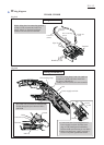
3. Mount Lock off button B to Pipe holder (R)
so that the notch aligns to the triangle mark
as drawn below.
Note:
Make sure that 2 pcs. of Rubber pin 6
are set in place.
Triangle mark on
Pipe holder (R)
Lock off button B
4. While aligning the triangle mark of Lock sleeve to
the symbol of “Unlock” on Handle (L), push Lock
sleeve toward Handle complete until it clicks.
And turn Lock sleeve until its triangle mark aligns
to the symbol of “Lock” on Handle (R).
Handle (L)
Lock
sleeve
Pipe 25
Inner groove
as a guide rail for
Pipe 25 moving
Rubber sleeve 25
Handle (L)
Power supply
cord unit
Square projection of
Pipe cap
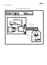
Caution label
Note: Face the caution label
upward as drawn in Fig. 8.
Symbol
of “Lock”
Symbol of
“Lock”
Handle (R)
Repair
P 7/ 12
Caution label
Caution label faced upward