


Repair
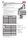
Circuit diagram
Wiring diagram
P 7/ 8
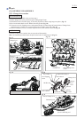
[2] ASSEMBLY/ DISASSEMBLY
[2]-5. Connecting rod, Shafts (cont.)
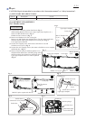
Assemble each wheel section in the reverse order of disassembly.
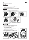
Distinguish Front shaft from Rear shaft by the white paint. (Fig. 30)
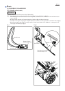
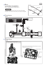
Connect Lead wires as drawn below.
Pass them through the square hole of Cowling.
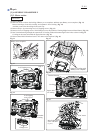
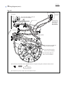
Route Lead wires in Switch box as drawn below so as not to
be pinched between ribs / bosses.
ASSEMBLING
Fig. 30
Fig. D-1
Fig. D-2
Front shaft
Rear shaft
white paint
Lock key
Lead unit
Terminal
Black Orange
Blue
White
Red Yellow
Color index of lead wire’s sheath
DC motor
Switch
Controller
Line filter
Switch lever
Lever
Power
supply
cord
M4x20 Pan
head screw
Tension spring 9