


APPENDIX A: EQUATORIAL WEDGE
There are two equatorial wedges used on Meade LX200
telescopes. Please read the section, below, that applies to your
telescope.
1. 8" Equatorial Wedge (For 7" and 8" LX200)
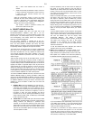
The equatorial wedge permits use of the 8" LX200 telescope in
an
astronomical, or "equatorial," mode. The wedge fits onto the field
tripod, described below, and accepts the base of the 7" or 8"
LX200 fork mount (Fig. 8).
NOTE: The Meade equatorial wedge is designed solely for use in
conjunction with the Meade field tripod. The wedge should
never be used without the field tripod (e.g., by placing the
wedge alone on a table top and then mounting the telescope on
the wedge). The 7" or 8" LX200, placed onto the equatorial
wedge alone without the field tripod attached to the wedge may
become seriously imbalanced, to the point where the telescope
may actually tip over.
The equatorial wedge for the 7" and 8" LX200 telescope is of
modern design, with several important features incorporated to
simplify and facilitate telescope operation. After using the wedge,
you will find that the functional design features included are of very
significant value in routine telescope operations. Features included
are:
• Attachment of the wedge to the field tripod by means of only
one manual knob.
• Quick azimuth adjustment by loosening the manual knob as
described above.
• Bubble level for rapid tripod/wedge leveling.
• Etched latitude scale for fast adjustment of the latitude angle.
To assemble the equatorial wedge, follow this procedure (note
that all required wedge hardware and manual knobs are shipped
within the wedge carton);
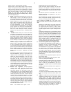
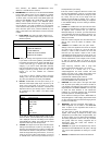
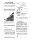
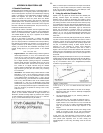
a. The wedge consists of two basic parts: the tilt plate and
wedge body (1 and 4, Fig. 8). Attach the tilt-plate to the
wedge body by threading in the four knobs provided. Two
knobs, with washers, should be used on each side of the
wedge body so that a total of 4 knobs attach the tilt plate to
the wedge body.
b. Place the wedge onto the field tripod with the central
threaded
rod of the tripod fitting through the center hole in the floor of
the wedge. Thread the 2-1/2" diameter manual
knob onto the
threaded rod of the tripod and firmly tighten the manual knob.
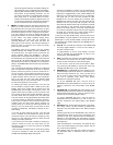
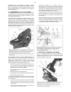
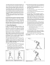
a. Azimuth Control
The azimuth control(Fig. 9) for the Meade equatorial wedge
and
field tripod is shipped in a plastic bag and includes the
following
parts:
• Azimuth base (large U shaped piece of aluminum)
• Azimuth arm (small T shaped piece of aluminum)
• 2 - Azimuth knobs
• 2 - 8-32 x 1/2" flat-head machine screws
• 2 - 8-32 x 1" round-head machine screws
To attach the azimuth control to your wedge and tripod, follow
these steps:
1. Remove the 4 set screws from the wedge and field tripod
(which plug the attachment holes) using a screwdriver.
2. Attach the azimuth arm to the equatorial wedge using the 2
ea. 8-32 x 1/2" flat-head machine screws.
3. Attach the azimuth base to the field tripod using the 2 ea.
8-32
x 1" round-head machine screws.
4. Thread the two azimuth adjustment knobs into the azimuth
base, until they just touch the azimuth arm.
The azimuth control is now ready to use. To adjust in azimuth,
loosen the 3" central wedge knob. Rotate the wedge by using the
two azimuth knobs in a push-pull manner. After positioning the
wedge, tighten the central wedge knob.
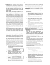
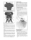
b. Deluxe Latitude Adjuster
The deluxe latitude adjuster (DLA) attaches directly to the
equatorial wedge and permits very precise adjustments in latitude
angle by the simple turning of one knob.
The equatorial wedge for Meade 7" or 8" Schmidt-Cassegrain
telescope is shipped with the main crossbar of the DLA already
installed. Loosen the two socket-head screws that lock the main
crossbar in place, to allow the crossbar to rotate slightly if needed.
Thread the long adjustment knob (3, Fig. 14) into the main
crossbar and position the end of the adjustment knob into the
cavity on the underside of the equatorial wedge tilt-plate. Tighten
the two socket-head screws locking the main crossbar into place.
The DLA is now ready to use. To make fine latitude adjustments,
follow this procedure:
1. Slightly loosen the knobs (5, Fig. 8), on each side of the
wedge.
2. Turn the DLA's adjustment knob (pressing against the
bottom of the tilt-plate), so that the tilt-plate moves in latitude
angle.
3. Re-tighten the two knobs, which were loosened in step 1,
above.
NOTE: When installing the tilt-plate to the wedge, note that it is a
tight fit and the sides must generally spread slightly to accept
25