16
Section 3: Adjustments
ZR44 & ZR52 (S/N 472619 and below) Zero Turning Radius Mowers Riding Mowers 356-059M 7/16/07
Land Pride
Table of Contents
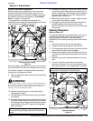
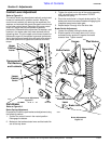
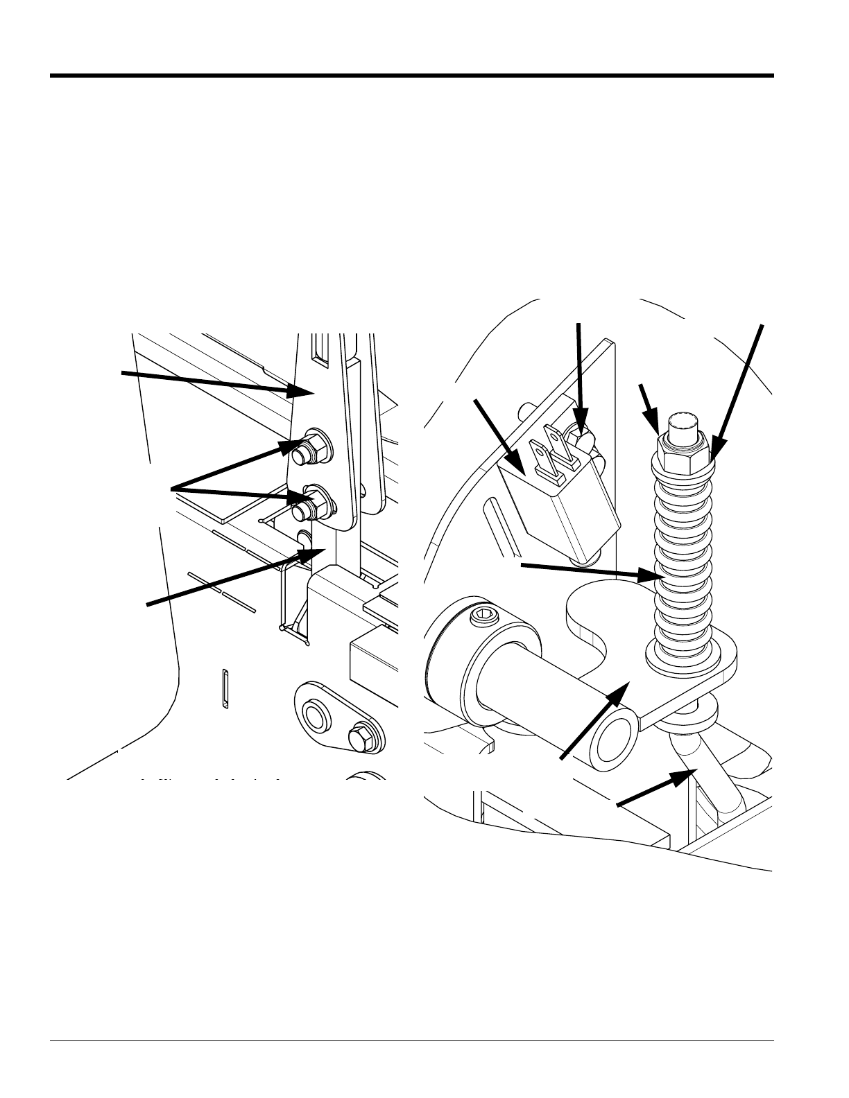
Control Lever Adjustment
Refer to Figure 3-4
The control levers may be adjusted vertically and pivoted
forward or backward for operator comfort. Adjust the
control levers vertically by removing the capscrews, flat
washers, and locknuts that attach the upper control levers
to the lower control levers. Reposition the upper control
levers to a height that fits the operator’s personal
preference. Reassemble the capscrews, flat washers, and
locknuts in the same order they were removed without
tightening them. Pivot the upper control levers forward or
backward to again fit the operator’s personal preference.
Verify that the control levers align with each other when in
the neutral position and tighten the locknuts to correct
torque.
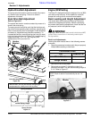
Park Brake
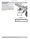
Refer to Figure 3-5:
Brake Spring Adjustment
Occasionally check the park brakes and adjustment using
the following method:
1. Position the control levers in the neutral position.
Disengage the blades.
2. Make sure the brake actuator lever and the brake link
are all the way down.
3. Tighten the nylock nut on top of the spring assembly
until it is touching the top flat washer. DO NOT
compress the spring.
4. Place the control lever in the park brake position. The
brake pawl should now be activated and engaging the
integrated pump/motor brake gear.
5. Repeat steps 2 through 4 for the other side.
Brake Switch Adjustment
1. Loosen the screws holding the brake switch.
2. Slide the switch all the way down until it is fully
activated (button pushed in) against the brake
actuator lever. Tighten screws.
Control Lever Adjustment
Figure 3-4
20685
Capscrewswith
Flat Washers,
and Locknuts
Lower
Control
Lever
Upper
Control
Lever
Brake Switch
Screws
Brake Actuator
Lever
Spring
Nylock Nut
Brake Link
Flat Washer
Brake Adjustments
Figure 3-5
20674


