


23
8/12/14
RTR12 & RTA12 Series (Serial No. 884764-) Rotary Tillers 311-785M
Land Pride
Section 4: Maintenance and Lubrication
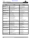
Table of Contents
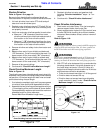
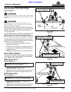
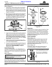
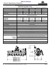
Refer to Figure 4-3:
1. Using a pencil or other marker scribe a line across the
exposed edges of the clutch plates and friction disks.
2. Carefully loosen each of the 8 spring retainer nuts by
exactly 2 revolutions. It will be necessary to hold the
hex end of the retainer bolt in order to count the exact
number of revolutions.
3. Start tractor and engage driveline for 2-3 seconds to
permit slippage of clutch plate and disk surfaces.
Disengage driveline and re-engage a second time for
2-3 seconds. Disengage driveline, shut off tractor
and remove key. Wait for all components to stop
before dismounting from tractor.
Clutch Run-In
Figure 4-3
4. Inspect clutch and ensure that the scribed markings
made on the clutch plates have changed position.
Slippage has not occurred if any two marks on the
friction disk and plate are still aligned. A clutch that
has not slipped must be disassembled to separate
the clutch plates from the friction disks. See “Clutch
Disassembly” instructions below.
5. Tighten each of the 8 spring retainer nuts on the
clutch housing exactly 2 revolutions to restore clutch
to its original setting pressure.
6. The clutch should be checked during the first hour of
operation and periodically each week. An additional
set of scribe marks can be added to check for
slippage. See “Clutch Assembly” to adjust for
proper spring length.
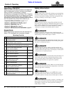
Clutch Disassembly
If the clutch run-in procedure, (See “Clutch Run-In” on
page 22), indicated that one or more of the friction disks did
not slip, the clutch must be disassembled to separate the
friction discs.
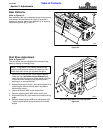
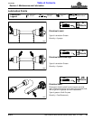
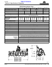
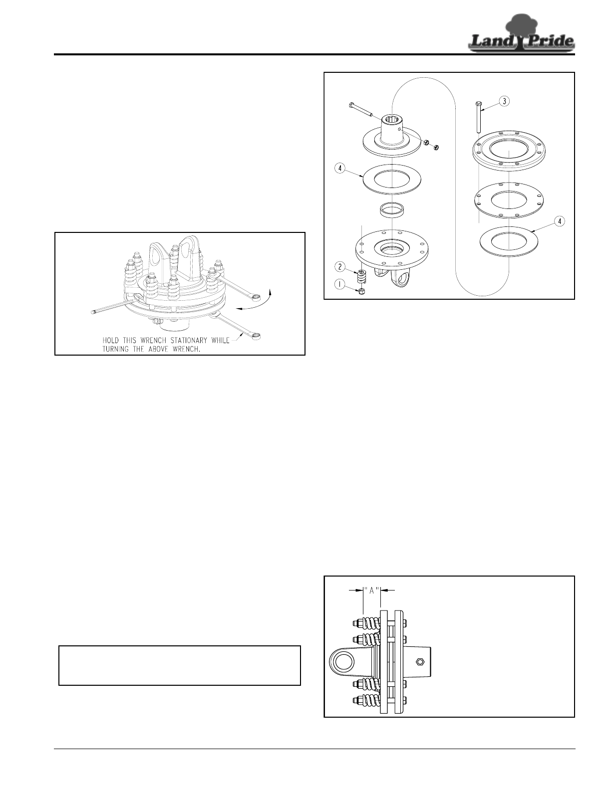
Refer to Figure 4-4:
See IMPORTANT NOTE above before disassembling
clutch. After measuring and recording each spring
length, remove spring retainer nuts (#1), springs (#2) and
bolts (#3). Each friction disc (#4) must then be separated
from the metal surface adjacent to it.
30560
IMPORTANT: Be Sure to measure and record
length (A”) of each clutch spring before
disassembling clutch.
Clutch Disassembly
Figure 4-4
Inspection
Inspect all parts for excessive wear and condition. Clean
all parts that do not require replacement.The original
friction disk thickness is 1/8" and should be replaced if
the thickness falls below 3/32". If the clutch have been
slipped to the point of “smoking”, the friction disks may be
damaged and should be replaced. Heat build-up may
also affect the yoke joints.
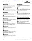
Clutch Assembly
Refer to Figure 4-4:
Reassemble each friction disk (#4) next to the metal
clutch plate it was separated from. Make certain all
bushing are replaced in the same location as when
removed. Install bolts (#3) through end plates and
intermediate plates as shown. Place springs (#2) over
each bolt and secure with nuts (#1).
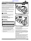
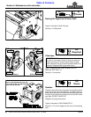
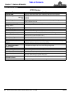
Refer to Figure 4-5:
Progressively tighten each spring retainer bolt until
correct spring height (“A” dimension) is reached.
Clutch Adjustment
Figure 4-5
30557
30559
A = Measured length of each spri
n
before disassembling slip clutch.
Use 1.15" for “A” dimension if
measurements were not taken.