


12
RTR12 & RTA12 Series (Serial No. 884764-) Rotary Tillers 311-785M
8/12/14
Section 1: Assembly and Set-Up
Table of Contents
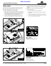
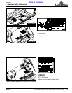
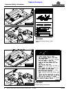
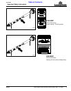
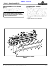
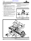
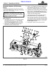
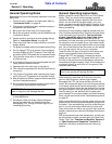
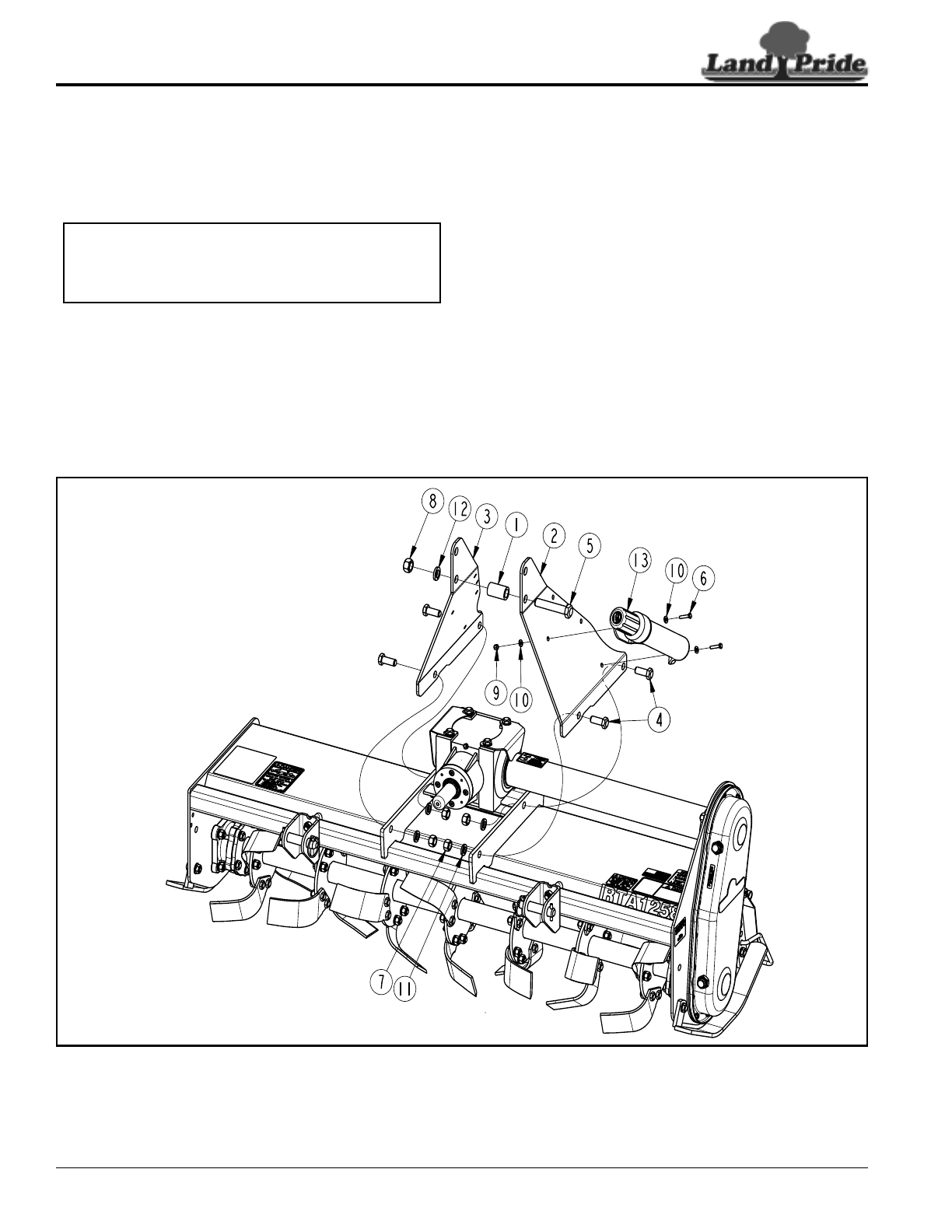
RTA Parking Stand, 3-Point Hitch & Driveline Assembly
Figure 1-5
30363A
Standard Rotation (RTA) Rotary
Tillers
The following are assembly instructions for standard
rotation tillers (RTA12 Series). See page 10 for reverse
rotation tillers (RTR12 Series).
RTA 3-Point Hitch Assembly
Refer to Figure 1-5:
1. Install upper right-hand hitch plate (#6) to gearbox
mounting frame with 5/8"-11 x 1 3/4" GR5 cap
screws (#9), spring lockwashers (#17), and hex
nuts (#12). Do not tighten hardware at this time.
2. Repeat step 1 to Install upper left-hand hitch
plate (#5) to gearbox mounting frame.
IMPORTANT: Parking stand (#3) and wire retaining
pin (#20) must be installed at the correct height
before continuing. See “Parking Stand Installation”
on page 9 for special instructions.
3. Install 1 1/4" OD spacer (#1) between upper 3-Point
hitch plates (#5 & #6) with 3/4"-10 x 4" GR5 cap
screw (#10), lockwasher (#18) and hex nut (#13).
4. Tighten all hex nuts (#12 & #13) to the correct torque.
5. Attach manual storage tube (#22) to hitch plate (#5)
with 1/4"-20 x 1 1/4" GR5 cap screws (#11), flat
washers (#116) and nylock hex nuts (#15) as shown.
Tighten nuts to the correct torque.
6. Install driveline guard (#7) on backside of 3-Point
hitch plates with four 5/16" wing screws (#8).
7. Attach left-hand clevis (#4) to the square tube with
1/2" u-bolt (#21) and 1/2" hex lock nuts (#14). Make
certain clevis is oriented with hitch pin holes closest
to the top and the longer chamfer is on the bottom.
Do Not Tighten lock nuts.
8. Repeat step 7 above for the right-hand clevis.