


9
8/12/14
RTR12 & RTA12 Series (Serial No. 884764-) Rotary Tillers 311-785M
Land Pride
Section 1: Assembly and Set-Up
Table of Contents
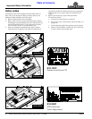
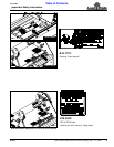
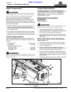
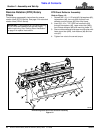
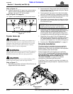
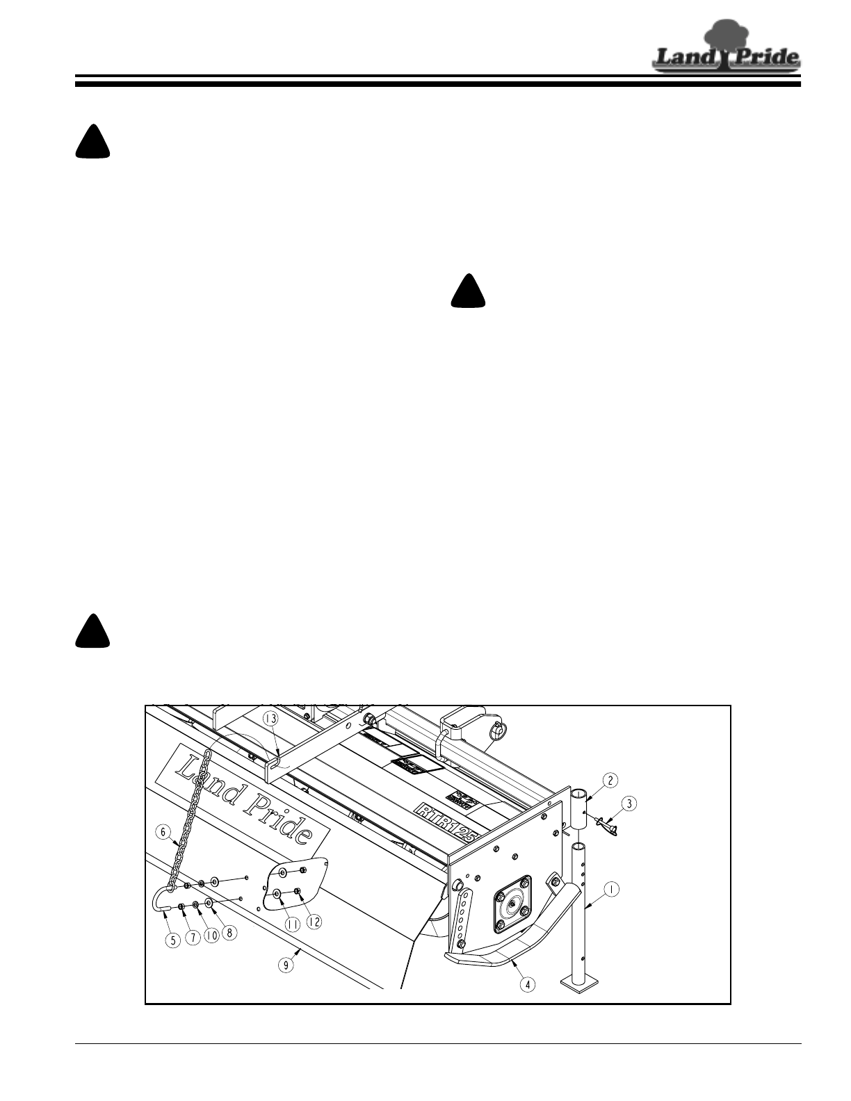
Support Leg & Rear Deflector Chain Assembly
Figure 1-1
RTR Series Shown
30728A
Section 1: Assembly and Set-Up
Torque Requirements
Check to make sure all nuts are tightened. Refer to
“Torque Values Chart” on page 32 to determine correct
torque values for common bolts. See “Additional
Torque Values” at bottom of chart for exceptions to
standard torque values.
RTR & RTA Parking Stand
Installation
Refer to Figure 1-1:
!
CAUTION
To avoid bodily injury caused by accidental falling of tiller,
stabilize unit with parking stand and support blocks.
1. Insert parking stand (#1) in support tube (#2).
2. Adjust parking stand to a height that will support the
tiller level while resting on skid shoes (#4).
3. Secure parking stand with wire retaining pin (#3).
Make sure wire retainer is hooked over the end of the
retaining pin.
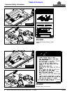
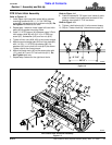
RTR & RTA Rear Chain Installation
Refer to Figure 1-1:
1. Insert u-bolt (#5) into one end of rear chain (#6).
2. Install two nuts (#7) onto u-bolt an equal distance
from the threaded end.
3. Insert u-bolt through lock washers (#10), flat
washers (#8), and holes in deflector shield (#9) that
are most vertically located under slot (#13).
4. Secure u-bolt (#5) to deflector shield (#9) with flat
washers (#11) and 3/8"-16 hex nuts (#12). Draw hex
nuts (#12) up snug and tighten hex nuts (#10) to the
correct torque.
5. Attach opposite end of rear chain (#6) to slot (#13).
Dealer Preparations
!
CAUTION
To avoid bodily injury caused by accidental falling of tiller,
securely support tiller on safe supporting stands or blocks.
This unit is shipped almost completely assembled.
Carefully follow instructions for final assembly.
Before attempting assembly check the following items.
Having all the needed parts and equipment readily at
hand will speed up your assembly task and will make the
job as safe as possible.
• Check for fasteners and pins that were shipped with
the tiller. Small hardware shipped loose from the
factory is contained in a bag. Larger parts are attached
to the shipping crate.
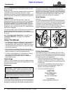
• Have ready for the assembly task a fork lift or loader
along with chains and safety stands sized for the job.
• Have a minimum of 2 people on hand during assembly.
Tractor Requirements
Tractor horsepower should be within the range noted
below. Tractors outside the horsepower range must not
be used.
Hitch Category . . . . . . . . . . . . . . . . . . . . 3-Point Cat. I
PTO Speed . . . . . . . . . . . . . . . . . . . . . . . . .540 RPM
Horsepower Requirements:
42" & 50" widths . . . . . . . . . . . . . . . . . . .15-35 HP
58" & 66" widths . . . . . . . . . . . . . . . . . . . .20-40 HP
74" Width . . . . . . . . . . . . . . . . . . . . . . . . .25-50 HP
!
WARNING
Ballast weights may be required to maintain steering control.
Refer to your tractor Operator’s Manual to determine proper
ballast requirements.