


18
Section 1: Assembly & Set-up
RCP2660, RCPM2660, RCP3060 and RCPM3060 Parallel Arm Rotary Cutter 316-111M
12/16/08
Land Pride
Table of Contents
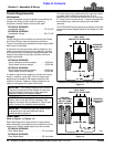
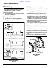
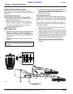
Tractor Controlled Cylinders
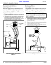
Refer to Figure 1-11:
Each tractor duplex outlet must be capable of infinite
variable flow control by the operator and should have
center detent “OFF” levers for controlled positioning of
the parallel arm and deck cylinders. If gauge wheels are
included, “ARM 2” and “DECK” levers must be capable of
being placed in float position.
1. Connect six hoses (2 per cylinder) to 3 duplex outlets
on your tractor as shown.
2. The hoses on each outlet should be connected such
that when the control lever is pushed “forward”, the
arm (or deck) extends. If the levers operate in reverse,
change hose hook-up at the duplex receptacle.
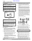
Hose Hook-up Without Solenoid Control
Figure 1-11
24638
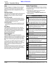
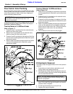
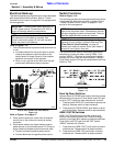
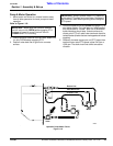
Breakaway Cylinder
Refer to Figure 1-12:
The breakaway cylinder protects the Rotary Cutter from
damage if cutter deck or parallel arm contacts a solid
object while moving forward. It does not protect cutter
from damage while backing up. Always make certain the
area behind the cutter is clear before backing up.
1. Locate tension bolt shown in Figure 5-7 on page 36
and remove from cutter before connecting hydraulic
hoses. Do Not reinstall tension bolt while using
hydraulic breakaway.
2. Attach quick disconnectadaptors (customer supplied)
to each breakaway hydraulic hose.
3. Attach breakaway hoses to a single duplex outlet on
the tractor as shown in Figure 1-12.
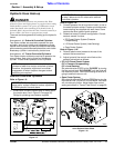
Breakaway Cylinder Hose Connections
Figure 1-12
IMPORTANT: See Figure 5-7 on page 36. A 1/2"
bolt is installed for shipping purposes only. This bolt
must be remove before connecting the hydraulic
hoses to the tractor.
12256