


42
Section 5: Maintenance & Lubrication
RCB6610 & RCBM6610 Series 2 S/N 944730+ Rotary Cutters 330-584M
11/11/12
Table of Contents
Cutter Blade Maintenance
!
DANGER
Always disconnect main driveline from tractor PTO before
servicing underside of cutter. PTO can be engaged if tractor is
started causing cutter damage, bodily injury or death.
!
DANGER
Always secure cutter deck in the up position with solid
supports before servicing underside of cutter. Never work
under equipment supported by hydraulics. Hydraulics can
drop equipment if controls are actuated or if hydraulic lines
burst. Either situation can drop the cutter instantly even when
power to the hydraulics is shut off.
!
WARNING
Do not operate cutter with blades that are bent, out-of-
balance, excessively worn, excessively nicked, or with blade
bolts that are excessively worn. Such blades can break loose
from the cutter at high speeds causing serious injury or death.
!
WARNING
Wait for blades to come to a complete stop before accessing
blade bolts through blade bolt access hole.
!
WARNING
Do not attempt to straighten a bent blade or weld on a blade.
Do not attempt to modify a blade such as hard surfacing, heat
treating, cold treating, or by any other method. Always
replace blades with a new Land Pride blade to assure safety.
!
CAUTION
ALWAYS wear gloves and eye protection while inspecting,
removing, sharpening, and replacing cutter blades.
Always inspect cutting blades before each use. Make
certain they are properly installed and in good working
condition. Replace any blade that is damaged, worn,
bent, or excessively nicked. Never try to straighten a bent
blade! Small nicks can be ground out when sharpening.
Refer to Figure 5-6 on page 42 when ordering Land Pride
replacement blade components.
Remove cutting blades and sharpen or replace as
follows:
1. Place tractor gear selector in park or set brake, shut
engine off and remove ignition key.
IMPORTANT: Replace cutting blades with genuine
Land Pride blades only. Blades must be replaced in
mating pairs. Not replacing both blades will result in
an out-of-balance condition that will contribute to
premature bearing breakdown on the spindle hub
and create structural cracks in the cutter housing.
2. Disconnect main driveline from tractor PTO and
secure cutter deck in the up position with solid
supports before servicing underside of cutter.
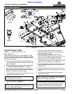
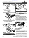
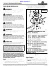
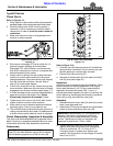
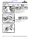
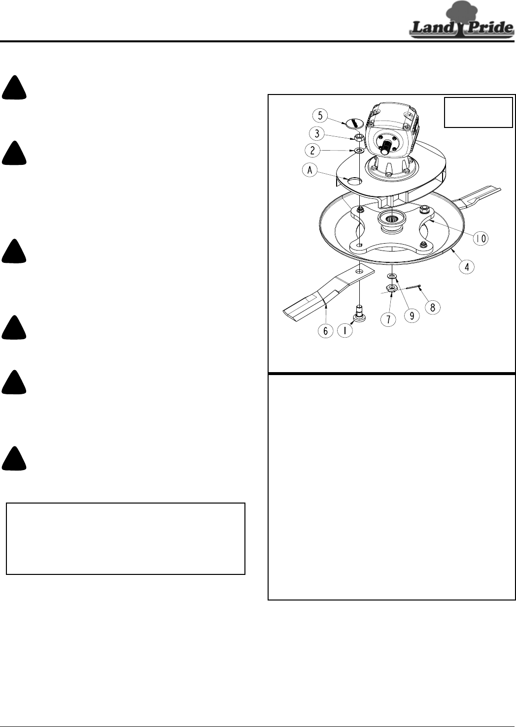
Cutter Blade Assembly (Standard Blade Rotation Shown)
Figure 5-6
Refer to Figure 5-6:
3. Remove rubber plug (#5) above cutter blade (#6).
Rotate blade bolt (#1) until in alignment with access
hole (A).
4. Unscrew lock nut (#3) to remove cutting blade (#6).
Blade bolt (#1) is keyed and will not turn freely.
30236
Use 1-11/16"
Socket Wrench
On Blade Nut #3
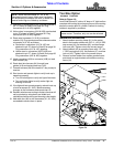
Blade Bolt Kit & Dishpan Part No’s.
Item Part No. Part Description
318-586A BLADE BOLT KIT (Item No’s 1, 2, & 3)
)
1 802-277C BLADE BOLT 1 1/8-12 x 3 7/16 WITH KEY
2 804-147C WASHER FLAT 1 HARD ASTMF436
3 803-170C NUT HEX TOP LOCK 1 1/8-12 PLATE
4 318-766H WELDMENT DISHPAN
5 840-273C PLUG LP 3" ID RUBBER
Standard Blades, Standard Rotation
6 820-168C CUTTER BLADE 1/2 x 4 x 29 CCW (Deck)
6 820-169C CUTTER BLADE 1/2 x 4 x 23 CCW (Wing)
Standard Blades, Special Reverse Rotation
6 820-249C CUTTER BLADE 1/2 x 4 x 29 CW (Deck)
6 820-170C CUTTER BLADE 1/2 x 4 x 23 CW (Wing)
Accessory Blades*
Low Lift Blades, Standard Rotation
6 820-478C CUTTER BLADE 1/2X4X29 LL CCW (Deck)
6 820-479C CUTTER BLADE 1/2X4X23 LL CCW (Wing)
*For additional information, see
“Low Lift Blade
Accessory”
on page 39