


23
Section 1: Assembly & Set-up
11/11/12
RCB6610 & RCBM6610 Series 2 S/N 944730+ Rotary Cutters 330-584M
Table of Contents
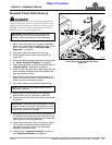
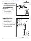
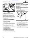
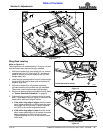
Lift Cylinder Mounting Position
Figure 1-21
Lift Cylinder Mounting Position
Refer to Figure 1-21:
Lift cylinder (#1) should be mounted in lower hole (A) if
cutter is equipped with 21" laminated tires or middle
hole (B) if cutter is supplied with 25.5" aircraft tires, or
upper hole (C) if 29" aircraft tires. Reposition lift cylinder
if it is not assembled in the correct hole.
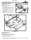
1. Park tractor and cutter on a level surface and raise
center deck fully up.
2. Without lowering cutter, shut tractor down properly
before dismounting. Refer to “Tractor Shutdown
Procedure” on page 14.
3. Place sturdy support blocks or jack stands under the
four corners of the center deck.
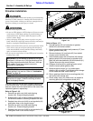
4. Remove all stroke control spacers (#4) from the
hydraulic cylinder rod.
5. Start tractor and lower center deck onto the support
blocks until hydraulic cylinder hitch pin (#2) is loose.
6. Shut tractor down properly before dismounting.
7. Remove hairpin cotter (#3) and hitch pin (#2).
8. Reposition hydraulic cylinder to the correct mounting
hole (A, B, or C) and reinsert hitch pin (#2). Secure
hitch pin with hairpin cotter (#3).
9. Start tractor, raise deck fully up, and then shut tractor
down again before dismounting.
10. Replace stroke control spacers (#4) and remove
support blocks.
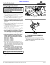
11. Start tractor and cycle hydraulic system by raising
and lowering center deck cylinder and wing folding
cylinders.
26611
26611
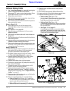
Rephase Lift Cylinders
The lift cylinders may be out of phase. See “Rephasing
Lift Cylinders” on page 34 for detailed instructions.
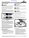
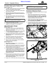
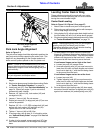
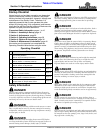
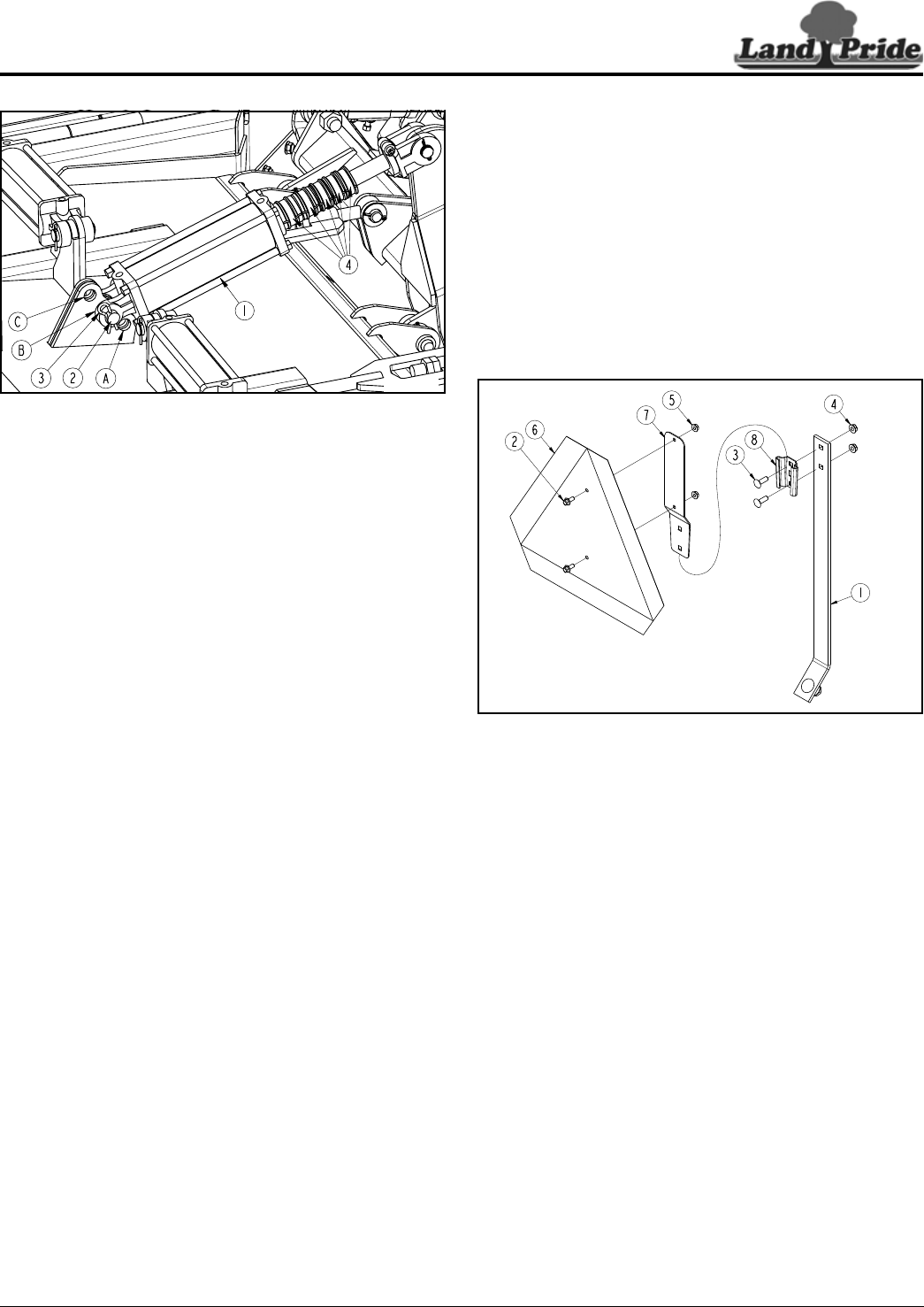
Slow Moving Vehicle Sign (SMV)
Refer to Figure 1-22:
Mounting blade (#7) is shipped from the factory bolted to
mounting socket (#8). The two should be separated and
reassembled as follows:
1. Remove hex flange nuts (#5), hex flange serrated
screws (#2) and SMV sign (#6) from mounting
blade (#7). Keep hardware for reuse.
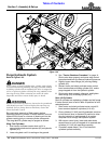
SMV Sign Assembly
Figure 1-22
2. Remove hex whiz nuts (#4), carriage bolts (#3),
mounting blade (#7), and mounting socket (#8) from
bracket (#1). Keep hardware for reuse.
3. Attach mounting socket (#8) to bracket (#1) with
existing carriage bolts (#3) and hex whiz nuts (#4).
Tighten whiz nuts to the correct torque.
4. Attach SMV sign (#6) to mounting blade (#7) with
existing hex flange serrated screws (#2) and hex
flange nuts (#5). Tighten nuts to the correct torque.
5. Insert mounting blade (#7) into mounting socket (#8).
30727