


17
Section 5 Maintenance and Lubrication
9/25/08
RC15, RC25, and RC35 Series Rotary Cutter 312-298M
Land Pride
Table of Contents
Section 5 Maintenance and Lubrication
Maintenance
Proper servicing and adjustment is the key to the long life
of any farm implement. With careful and systematic in-
spection, you can avoid costly maintenance, time and re-
pair.
After using your cutter for several hours, check all bolts to
be sure they are tight.
Replace any worn, damaged or illegible safety decals by
obtaining new decals from your Land Pride Dealer.
Service Cutting Blades
1. Both blades should be sharpened at the same angle
as the original cutting edge and must be replaced or
reground at the same time to maintain proper balance
in the cutting unit.
2. Both blades should weigh the same after sharpening.
3. When replacing or sharpening the cutter blades, ex-
amine bolts for excessive wear and replace if neces-
sary. To replace blades:
a. Order blade bolt Land Pride part # 802-277C.
b. Blade shim (#30), must be installed to insure a
tight and proper fit between the blade bolt and
blade. Too tight a fit may cause blade to not swing
back into proper cutting position after striking ob-
stacles. Too loose a fit will cause play between
blade bolt and blade resulting in excessive wear
on blade carrier, blade bolts and blades. Three
sizes of shims are available: 16 ga., part no. 312-
075D; 18 ga., part no. 312-082D; & 20 ga., part
no. 312-089D.
c. Torque blade bolt lock nut to 450 ft. pounds. Use a
3’ long pipe to achieve proper torque.
4. If replacing dishpan, nut on gearbox output shaft
should be torqued to 450 foot/pounds and cotter pin
installed in nut with legs securely bent around nut.
Shearbolt Driveline
Cutter drive components are protected from shock loads
by a 1/2" shear bolt. If shear bolt fails, replace with a 1/2"
x 3 1/2" long hex bolt, grade 2. Shear bolt failure can be
avoided by engaging the PTO slowly at low engine rpm.
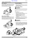
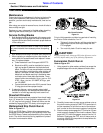
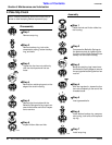
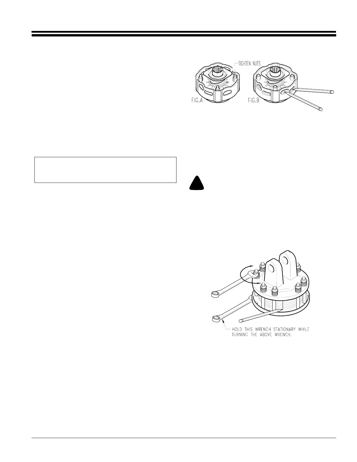
Walterscheid Slip Clutch Run-In
Refer to Figure 5-1:
RC15 and RC25 Rotary Cutters drive components are
protected from shock loads by a two plate slip clutch and
the RC35 Rotary Cutters are protected by a four plate slip
clutch. The clutch should slip during operation to protect
the cutter from excessive loads.
Prior to initial operation and after long periods of inactivity,
the Friction Clutch should be "run-in".
a. Tighten all 4 nuts uniformly until the spring load is
low enough that the clutch slips freely with the
PTO engaged.
b. Turn nuts fully back. Clutch is ready for use.
!
CAUTION!
Engage parking brake, disengage PTO, shut off tractor, and re-
move key before making any of the following adjustments.
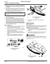
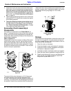
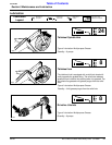
Eurocardan Clutch Run-In
Refer to Figure 5-2:
1. Using a pencil or other marker, scribe a line across the
exposed edges of the clutch plates and friction disks.
2. Carefully loosen each of the 8 spring retainer nuts on
the clutch housing a total of EXACTLY 2 revolutions. It
will be necessary to hold the hex end of the retainer
bolt in order to count the exact number of revolutions.
3. Start the tractor and engage the PTO drive for 2-3 sec-
onds to permit slippage of the clutch surfaces. Disen-
gage the PTO, then re-engage a second time for 2-3
seconds. Disengage the PTO, shut off tractor and re-
move key. Wait for all components to stop before dis-
mounting from tractor.
NOTE: Care should be taken in order not to remove
any more material than necessary when sharpening
blades.
Slip Clutch Driveline
Figure 5-1
14221
Clutch
Figure 5-2
13693