


13
Section 3 Adjustments
9/25/08
RC15, RC25, and RC35 Series Rotary Cutter 312-298M
Land Pride
Table of Contents
Section 3 Adjustments
Cutting Height
There are 4 primary adjustments that should be made pri-
or to actual field operations:
a. Deck level from left to right
b. Tractor top link length
c. Tractor lower link height
d. Tailwheel height
Proper adjustment of each of these items will provide for
higher efficiency, improved cutting performance and long-
er blade life. The following tools will be needed:
a. Pliable tape measure
b. Spirit or carpenters level
c. Open end or hex end wrench or socket set
d. Protective gloves
Having completed 3-Point Tractor Hookup in the “Assem-
bly and Setup” section on page 10 locate the tractor on a
flat level surface.
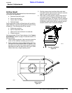
1. Use the tractor’s hydraulic 3-point control to lower the
cutter until the tailwheel contacts ground surface.
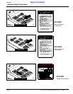
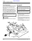
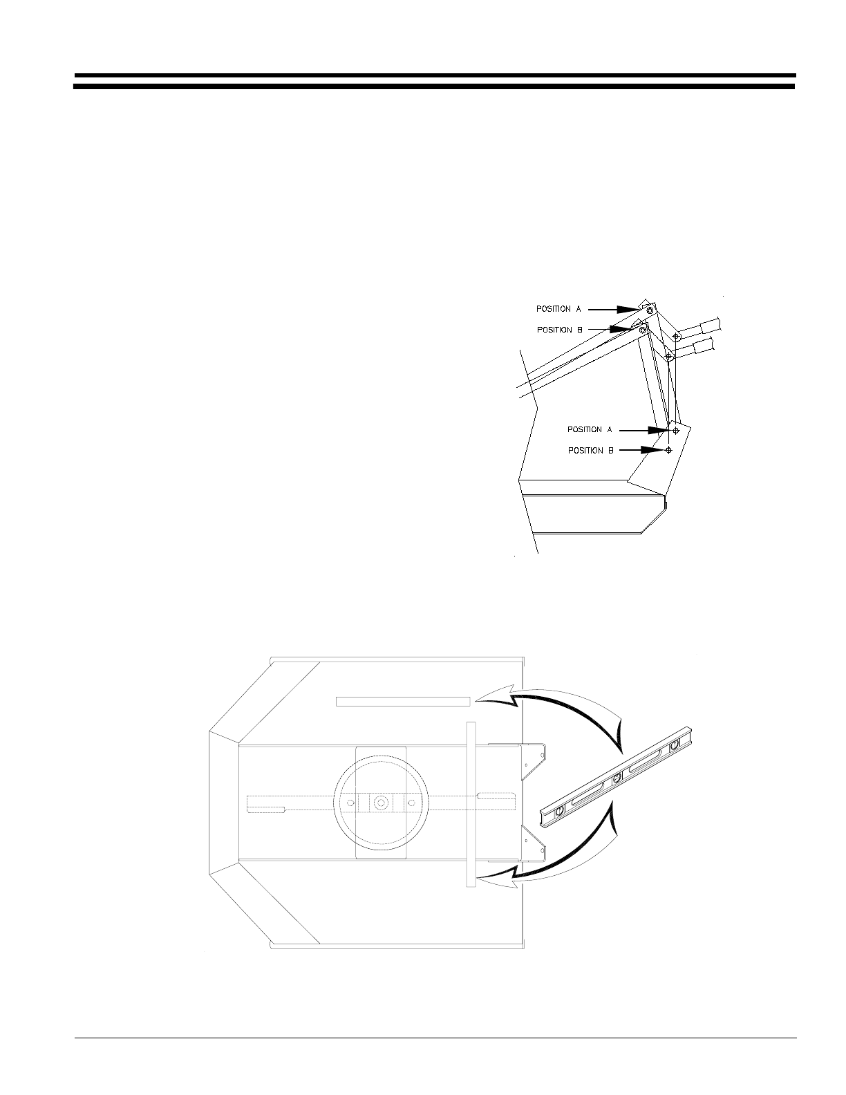
2. Place a spirit level or other suitable leveling device on
the front of the cutter deck as shown in Figure 3-1. Ad-
just either one or both of the tractors lower link height
adjustments to level the deck from left to right. Some
tractors have only a single adjusting crank.
Deck Leveling
Figure 3-1
14240
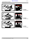
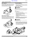
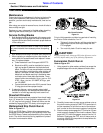
3. Similarly, place a level on either of the main deck
channels. Use the tractors 3-point hydraulic control to
level the cutter deck from front to rear.
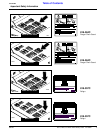
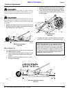
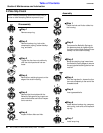
4. With cutter in cutting position, adjust tractor lop link
until upper hitch pin is aligned vertically with lower
hitch pins, see Figure 3-2. Position "A" is for standard
category hitch tractors and position "B" is for smaller
horsepower rated tractors without adequate ground
clearance when cutter is raised for transport.
Top Link Adjustment
Figure 3-2
10419